Apparatus for production of crystal of group III element nitride and process for producing crystal of group III element nitride

a technology of nitride crystals and manufacturing apparatus, which is applied in the direction of crystal growth process polycrystalline material growth, etc., can solve the problems of reducing the dislocation density, complicated implementation of the method, and affecting the quality of crystals obtained through vapor phase epitaxy, etc., to achieve easy control of the density of dopants in crystals, improve and adversely affect the quality of crystals obtained

Inactive Publication Date: 2007-07-12
MORI YUSUKE +1
View PDF9 Cites 25 Cited by
  • Summary
  • Abstract
  • Description
  • Claims
  • Application Information

AI Technical Summary

Benefits of technology

[0011] In order to achieve the above-stated object, the inventors of the present invention have conducted a series of investigations. During the course of the research, the inventors found that impurities mixed into gas that is to be introduced into a reactor vessel adversely affect the quality of obtained crystals. As a result of additional research, it further was found that the mixing of impurities into the gas to be introduced into the reactor vessel is caused by a pressure-resistant vessel. That is, a conventional apparatus is configured so that gas is introduced into a pressure-resistant vessel, and such gas is then introduced into a reactor vessel. With this configuration, impurities such as water and oxygen, which are attached to a heater, a heat insulator, an inner wall of the pressure-resistant vessel and the like, are mixed into the site of the crystal growth, which adversely affects the quality of crystals obtained. On the other hand, according to the apparatus and the manufacturing method of the present invention, the gas containing nitrogen is introduced directly to the reactor vessel without passing through the pressure-resistant vessel, thus preventing impurities attached to the heater, the heat insulator, the pressure-resistant vessel, etc., from mixing into the site of the crystal growth. As a result, it is possible to improve the quality of the crystals obtained. Further, by controlling impurities, gas with reduced impurities can be supplied always from the gas supplying device, and therefore the density of dopants in crystals can be controlled easily, resulting in improved controllability of the carrier density.
[0012] Further, in a conventional apparatus, the following problem occurs frequently: when crystals are grown using alkali metal, the evaporating alkali metal aggregates at a gas inlet and a pipe connected to the gas inlet, with which the gas inlet and the pipe are clogged, causing a failure in the supply of gas containing nitrogen to a reactor vessel. In order to cope with such a problem, the inventors of the present invention further conducted investigation. As a result, it was found that this was caused by the fact that gas hardly flows in a reactor vessel. That is, in a conventional apparatus, a nitrogen component only is supplied through a gas inlet into a reactor vessel that is subjected to reaction, and gas hardly flows, thus causing aggregation of alkali metal or the like at the gas inlet and a pipe connected to the gas inlet due to diffusion. Additionally, in some cases, an alkali metal and an alkaline-earth metal flow into a pipe connected to a gas inlet and a gas supplying device and chemically attack them, and a dissolved substance generated by the chemical-attacking is mixed into the site of the crystal growth, which adversely affects the quality of crystals obtained. On the other hand, according to the apparatus and the manufacturing method of the present invention, a reactor vessel used includes a gas outlet in addition to a gas inlet, and gas containing nitrogen, introduced through the gas inlet, that is not subjected to reaction in the reactor vessel can be exhausted through the gas outlet, and therefore gas can flow continuously in a fixed direction in the reactor vessel. Thus, the aggregation of an alkali metal, an alkaline-earth metal, etc, at the gas inlet, the gas outlet and the pipes connected therewith and the inflow of an alkali metal, an alkaline-earth metal, etc, into a gas supplying device through the gas inlet can be prevented. As a result, the quality of crystals obtained further can be improved.

Problems solved by technology

However, the quality of crystals obtained through vapor phase epitaxy has a problem.
More specifically, crystals obtained by this method generally have a dislocation density of 108 cm−2 to 109 cm−2 and thus reducing dislocation density has been an important issue.
With this method, the dislocation density can be reduced, but the implementation thereof is complicated, which poses a problem in practical utilization.

Method used


Image

  • Apparatus for production of crystal of group III element nitride and process for producing crystal of group III element nitride
  • Apparatus for production of crystal of group III element nitride and process for producing crystal of group III element nitride
  • Apparatus for production of crystal of group III element nitride and process for producing crystal of group III element nitride

Examples


example 1

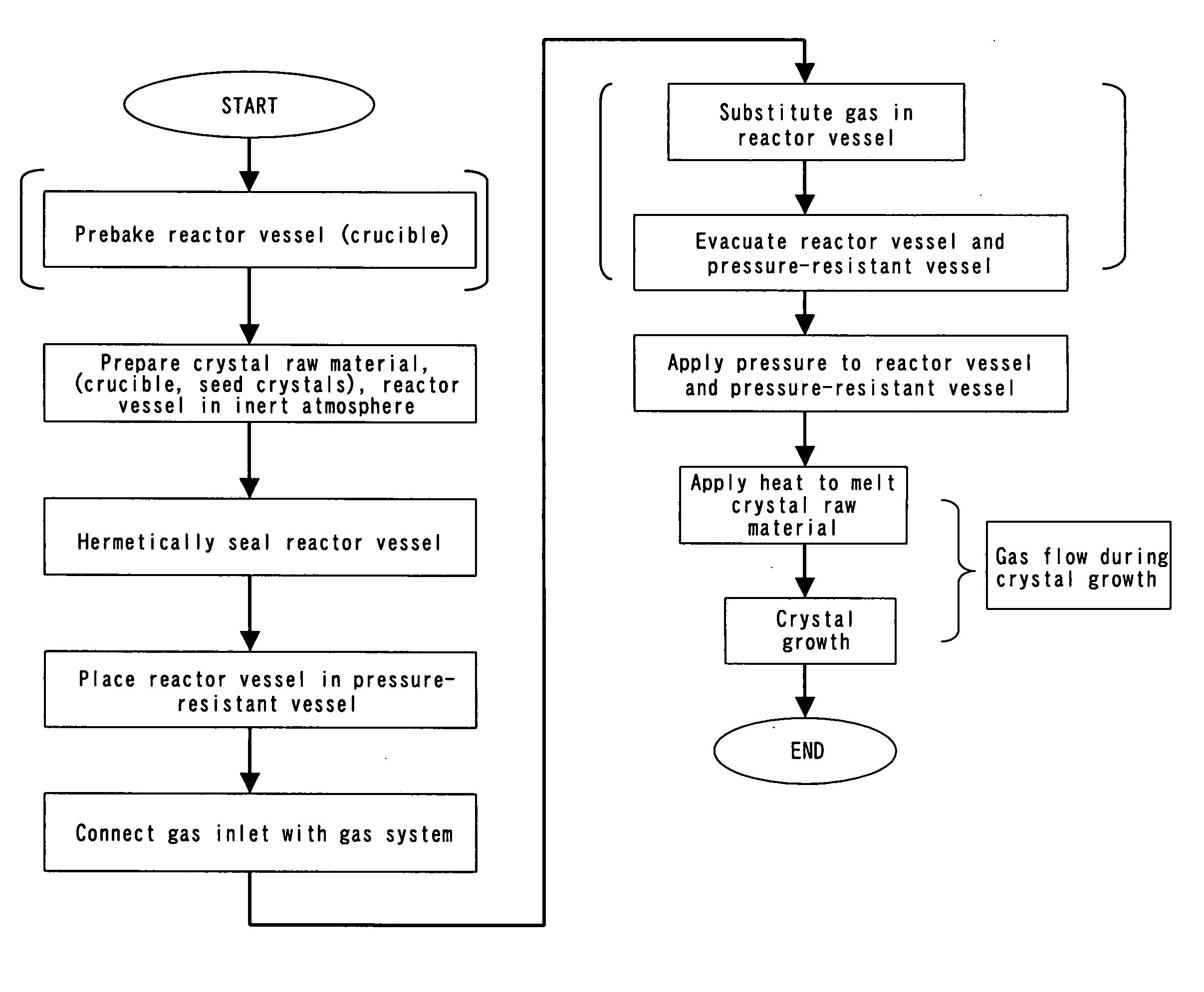
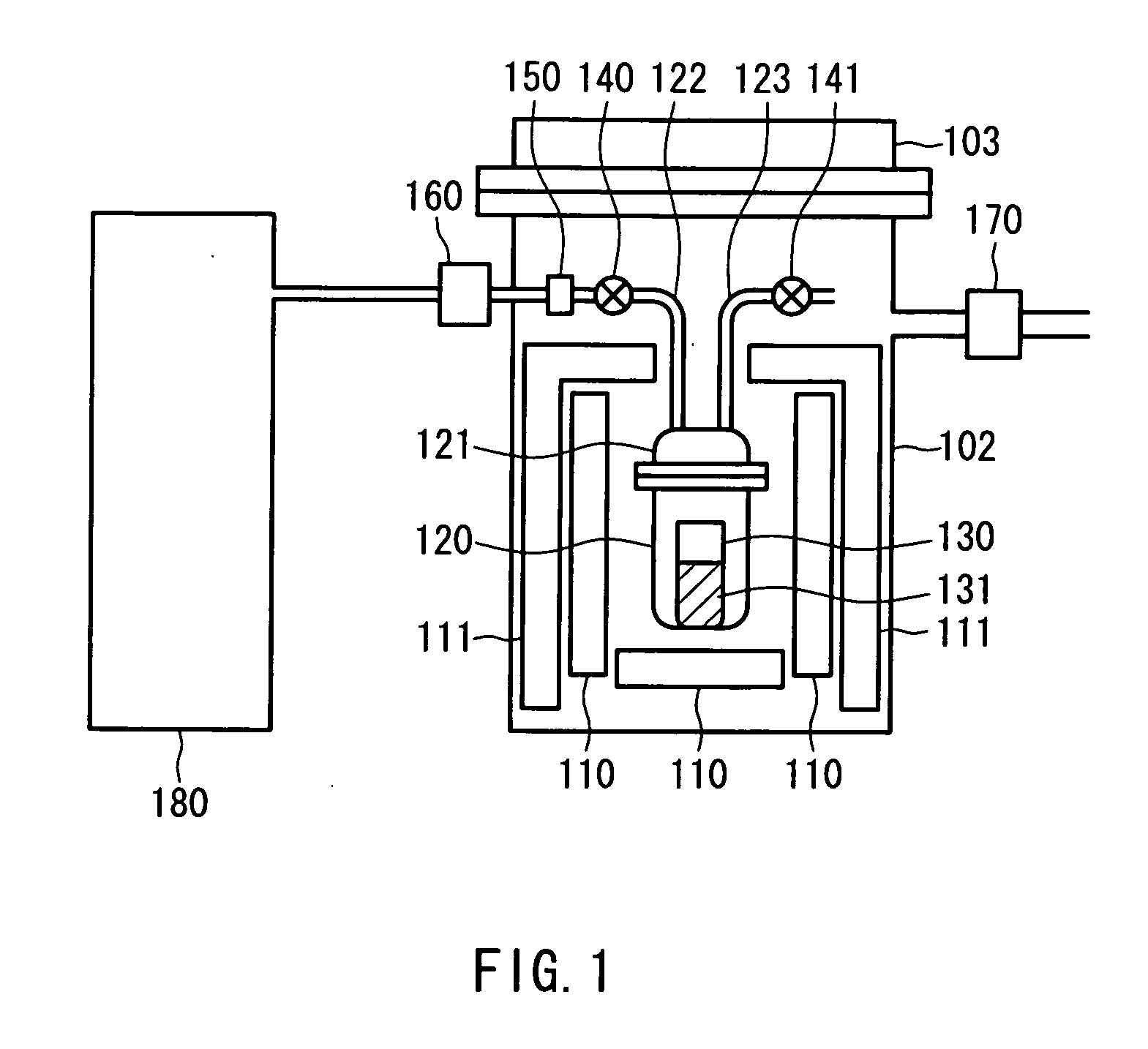
[0060]FIG. 1 shows the configuration of one example of an apparatus according to the present invention. As illustrated, this apparatus is provided with a gas supplying device 180, a reactor vessel 120, a pressure-resistant vessel 102 and a heater 110. The reactor vessel 120 is stored in the pressure-resistant vessel 102, and a crucible 130 can be placed in the reactor vessel 120. A lid 103 is placed at the top of the pressure-resistant vessel 102 so as to enable hermetic sealing of the pressure-resistant vessel 102. A heat insulator 111 is placed closer to an inner wall of the pressure-resistant vessel 102, and the heater 110 is placed in a space surrounded by this heat insulator 111. The reactor vessel 120 is placed so as to be surrounded by this heater 110. The reactor vessel 120 can be closed at the top with a lid 121. A pipe 122 is connected to the gas supplying device 180, and a gas flow rate regulator 160, a junction 150 and a gas open / close mechanism (valve) 140 are placed al...

example 2

[0077] Next, another example of the configuration of an apparatus of the present invention is shown in FIG. 4. As illustrated in this drawing, this apparatus has the same configuration as that of the apparatus shown in FIG. 1 except that a recovery device 490 is connected to a pressure regulator 470. The manufacturing method using this apparatus also is the same as in the above. In this example, since the recovery device is provided, emission of an alkali metal, an alkaline-earth metal, etc., evaporating from the crystal raw-material solution to the air outside of the apparatus can be prevented. In FIG. 4, numeral 480 denotes a gas supplying device, 460 denotes a gas flow rate regulator, 450 denotes a junction, 440 and 441 denote gas open / close mechanisms (valves), 402 denotes a pressure-resistant vessel, 403 denotes a lid of the pressure-resistant vessel 402, 420 denotes a reactor vessel, 421 denotes a lid of the reactor vessel 420, 430 denotes a crucible, 410 denotes a heater and ...

example 3

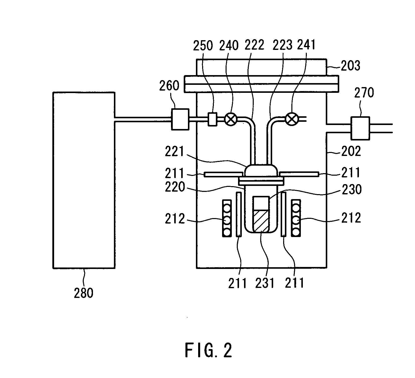
[0078] Next, still another example of the configuration of an apparatus of the present invention is shown in FIG. 2. The apparatus of this example has the same configuration as that of the apparatus shown in FIG. 1 except that a high-frequency heater is used as the heater and the arrangement of the heat insulator is changed correspondingly in the above-stated apparatus of Example 1. The manufacturing method using this apparatus also is the same as in the above. As shown in FIG. 2, in this apparatus, a heat insulator 211 is placed around a reactor vessel 220, which is surrounded by a high-frequency heater 212. Since the high-frequency heater 212 is used, a ceramic material such as alumina may be used for the reactor vessel 220 and a conductive metal such as tungsten or tantalum may be used as a crucible 230, whereby heat can be applied to portions to be heated effectively. Further, according to this example, since heat is applied to the crucible 230 and a crystal raw material 231 onl...


PUM

PropertyMeasurementUnit
inner diametersaaaaaaaaaa
lengthaaaaaaaaaa
lengthaaaaaaaaaa

Abstract

A manufacturing apparatus of Group III nitride crystals and a method for manufacturing Group III nitride crystals are provided, by which high quality crystals can be manufactured. For instance, crystals are grown using the apparatus of the present invention as follows. A crystal raw material (131) and gas containing nitrogen are introduced into a reactor vessel (120), to which heat is applied by a heater (110), and crystals are grown in an atmosphere of pressure applied thereto. The gas is introduced from a gas supplying device (180) to the reactor vessel (120) through a gas inlet of the reactor vessel, and then is exhausted to the inside of a pressure-resistant vessel (102) through a gas outlet of the reactor vessel. Since the gas is introduced directly to the reactor vessel (120) without passing through the pressure-resistant vessel (102), the mixture of impurities attached to the pressure-resistant vessel (102) and the like into the site of the crystal growth can be prevented. Further, since the gas flows through the reactor vessel (120), there is no aggregation of an evaporating alkali metal, etc., at the gas inlet or the like, and such an alkali metal does not flow into the gas supplying device (180). As a result, the quality of Group III nitride crystals obtained can be improved.

Description

TECHNICAL FIELD [0001] The present invention relates to a manufacturing apparatus of Group III nitride crystals and a method for manufacturing Group III nitride crystals. BACKGROUND ART [0002] Group III nitride compound semiconductor such as gallium nitride (GaN) (hereinafter also referred to as a “Group III nitride semiconductor” or a “GaN-based semiconductor”) has been gaining attention as a material for semiconductor elements that emit blue or ultraviolet light. A blue laser diode (LD) is used for high-density optical disk devices or displays while a blue light emitting diode (LED) is used for displays, lighting, etc. It is expected to use an ultraviolet LD in the field of biotechnology or the like and an ultraviolet LED as an ultraviolet source for a fluorescent lamp. [0003] Generally, Group III nitride semiconductor substrates (for example, GaN substrate) that are used for LDs or LEDs are formed by vapor phase epitaxy. For instance, Group III nitride crystals are grown heteroep...

Claims


Application Information

Patent Timeline
Patent Type & Authority Applications(United States)
IPC IPC(8): C30B11/00C30B23/00C30B21/06B01J3/04C30B9/00C30B9/10C30B29/38C30B35/00H01L33/06H01L33/32
CPCC30B9/10C30B29/403Y10T117/1064C30B35/00Y10T117/1096C30B29/406
Inventor MINEMOTO, HISASHIKITAOKA, YASUOKIDOGUCHI, ISAOMORI, YUSUKEKAWAMURA, FUMIOSASAKI, TAKATOMOUMEDA, HIDEKAZUTAKAHASHI, YASUHITO
Owner MORI YUSUKE
Why Eureka
Try Eureka