Glass optical waveguide

a glass and optical waveguide technology, applied in the field of glass optical waveguides, can solve the problems of difficult to achieve downsizing, difficult to obtain desired transmission band, difficult to form arrays, etc., and achieve the effect of compact optical light guides and low propagation loss

Inactive Publication Date: 2007-07-19
ASAHI GLASS CO LTD
View PDF1 Cites 11 Cited by
  • Summary
  • Abstract
  • Description
  • Claims
  • Application Information

AI Technical Summary

Benefits of technology

[0028] According to the optical waveguide of the present invention, it is possible to obtain an optical waveguide having a core made of a glass material containing total at least 35% in mass % of at least one type of oxide selected from the group consisting of Bi2O3, Sb2O3, PbO, SnO2 and TeO2, and showing low propagation loss.
[0029] The glass optical waveguide of the present invention is suitable for an optical amplifying waveguide, nonlinear optical waveguide or the like in 0.4 to 2 μm wavelength band, and the glass optical waveguide can amplify light of 1.45 to 1.64 μm wavelength band such as signal light of C band (1,530 to 1,565 nm). Further, according to the present invention, a compact optical light guide can be obtained.

Problems solved by technology

However, in an optical fiber having a core made of an Er-doped silica glass type glass, there are such problems as difficulty in obtaining desired transmission band, difficulty in achieving downsizing and difficulty in constituting an array.
The causes of optical attenuation in a waveguide are coupling loss at a light input / output end and transmission loss in the waveguide itself.
This causes to increase radiation loss.

Method used


Image

  • Glass optical waveguide
  • Glass optical waveguide
  • Glass optical waveguide

Examples


example 1

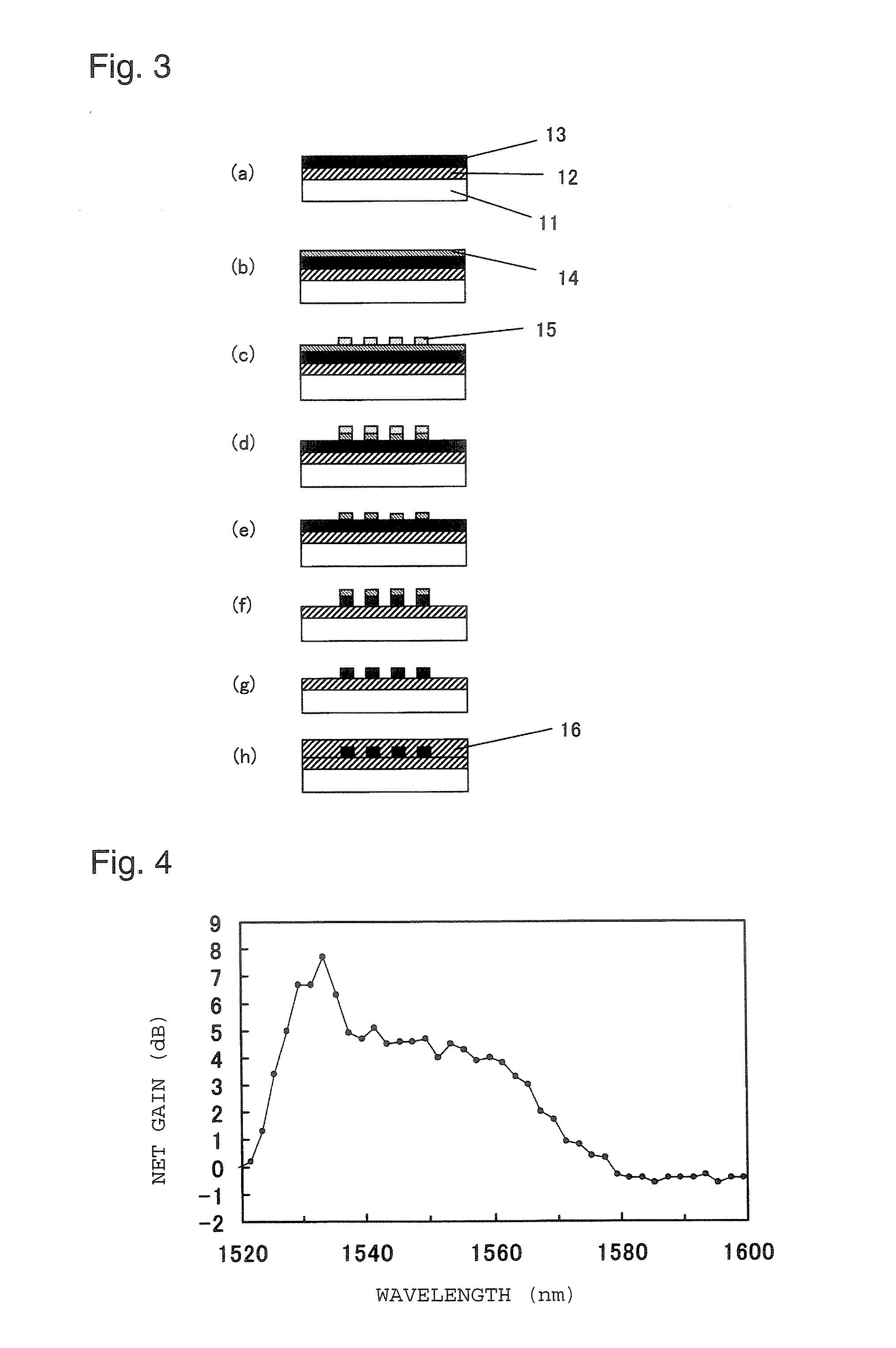
[0117] On a soda lime silica glass disc-shaped substrate 11 (1 mm thick, 76.2 mm in diameter), an underlayer clad film 12 of 6.6 μm thick was formed. Namely, using a T2 target, sputtering was carried out under the conditions that the substrate temperature was 20° C., argon and oxygen as sputtering gases were flown at flow rates of 30 cm3 / min and 0.5 cm3 / min respectively as converted as standard conditions, the pressure was 0.3 Pa, applied RF power was 100 W and sputtering time was 66 hours. When X-ray diffraction measurement was made to a glass film formed on the substrate, no peak was recognized in a diffraction pattern, and it was confirmed that the glass film was amorphous.

[0118] Then, a core film 13 of 3.3 μm thick was formed on the underlayer clad film. Namely, using a T1 target, sputtering was carried out under the conditions that the substrate temperature was 20° C., argon and oxygen as sputtering gases were flown at flow rates of 30 cm3 / min and 0.75 cm3 / min respectively in ...

example 2

[0128] On a soda lime silica glass disc-shaped substrate 11 (1 mm thick, 76.2 mm in diameter), an underlayer clad film 12 of 8.4 μm thick was formed. Namely, using a T2 target, sputtering was carried out under the conditions that the substrate temperature was 20° C., argon and oxygen as sputtering gases were flown at 30 cm3 / min and 0.75 cm3 / min respectively in terms of values under standard conditions, the pressure was 0.3 Pa, applied RF power was 100 W and sputtering time was 60 hours. When an X-ray diffraction measurement of the glass film formed on the substrate was carried out, no peak was recognized in the diffraction pattern and it was confirmed that the glass film was amorphous.

[0129] Then, on the underlayer clad film, a core film 13 of 3.3 μm thick was formed. Namely, using a T2 target, sputtering was carried out under the conditions that substrate temperature was 20° C., argon and oxygen as sputtering gases were flown at flow rate of 30 cm3 / min and 0.5 cm3 / min respectively...

example 3

[0139] Using a target T2, sputtering was carried out under the same conditions as those of Example 2 to form, on a soda lime silica glass substrate, an underlayer clad, a core and a protection film which becomes an upper layer clad, were formed and a mask film of 1.3 μm thick was formed under the same conditions, and thereafter, etching was carried out under the same conditions of Example 2 to pattern the mask.

[0140] Subsequently, resist on the mask film was removed under the same conditions of Example 2, and using the mask film thus patterned, the glass film was NLD etched under the following conditions. Namely, flow rates of AR gas and C3F8 gas were 49.5 cm3 / min and 5.5 cm3 / min respectively in terms of values under standard conditions. Further, at this time, the pressure was 0.2 Pa, discharge electric power was 1,000 W in terms of antenna power and 250 W in terms of bias power, currents of three neutral magnetic field generation coils arranged in vertical direction of a chamber w...


PUM


Abstract

In a glass optical waveguide having a core containing at least one oxide selected from the group of glass-constituting oxides consisting of Bi2O3, Sb2O3, PbO, SnO2 and TeO2, large transmission loss of light which occurs when the cross-sectional shape of the core is rectangle, is reduced. A glass optical waveguide which contains at least total 35% in mass % of at least one type of the above glass-constituting oxides, wherein the cross-sectional shape of the core is trapezoidal, among two parallel sides of the trapezoid, a long side is in a substrate side and among four sides constituting the trapezoid, angles of two oblique sides to the long side are each within a range of from 60 to 80°.

Description

TECHNICAL FIELD [0001] The present invention relates to a glass optical waveguide. BACKGROUND ART [0002] In order to develop an optical amplifier to be used for the optical communication field of wavelength division multiplex system (WDM), a glass fiber having a core containing a rare earth element has been eagerly researched and developed. However, in an optical fiber having a core made of an Er-doped silica glass type glass, there are such problems as difficulty in obtaining desired transmission band, difficulty in achieving downsizing and difficulty in constituting an array. As a measure against these problems, an optical fiber having a core made of an Er-containing Bi2O3 type glass material (refer to e.g. Patent Document 1) or an optical waveguide having an optical amplifying core made of a glass material formed on a substrate, has been proposed and developed. [0003] As a glass waveguide, a silica glass type glass waveguide is commonly known. As a method for forming a fine waveg...

Claims


Application Information

Patent Timeline
Patent Type & Authority Applications(United States)
IPC IPC(8): G02B6/10
CPCG02B6/122G02B6/136H01S3/17H01S3/0637H01S3/1608H01S3/0632G02B6/12H01S3/10G02B6/13H01S3/06
Inventor KONDO, YUKIONO, MOTOSHISUGIMOTO, NAOKI
Owner ASAHI GLASS CO LTD
Why Eureka
Try Eureka