
Hard coat film, antireflection hard coat film, optical element and image display

a technology of hard coat and optical element, applied in the field of hard coat film, anti-reflection hard coat film, optical element and image display, can solve the problems of difficult to strike a balance between, and achieve the effects of suppressing cracking or curling, reducing inference fringes, and high hardness

Inactive Publication Date: 2007-08-02
NITTO DENKO CORP
View PDF5 Cites 64 Cited by
  • Summary
  • Abstract
  • Description
  • Claims
  • Application Information

AI Technical Summary

Benefits of technology

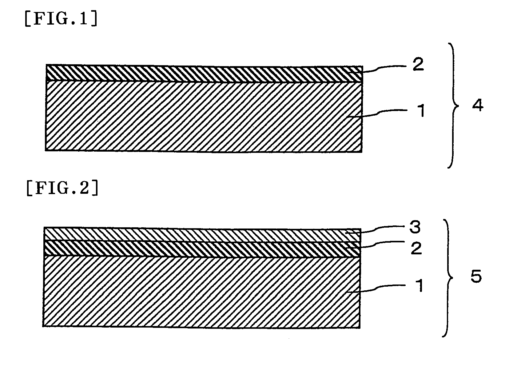
[0011] It is an object of the invention to provide a hard coat film comprising a hard coat layer, which is a cured coat layer, provided on at least one side of a transparent plastic film substrate, the hard coat layer having a high hardness and suppressed curling due to cracking and cure shrinkage.
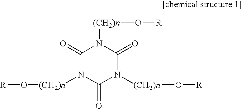
[0017] The invention gives elasticity and flexibility (bendability) to a hard coat layer using urethane acrylate (A) as a hard coat layer forming material. A crosslinking degree is increased and a high hardness in a hard coat layer is realized by using isocyanuric acid acrylate (B). Moreover the invention alleviates cure shrinkage, occurring in curing of a resin which forms the hard coat layer, by using inorganic ultrafine particles (C) in use. With such a construction adopted, a hard coat film of the invention has a high hardness of pencil hardness of 3H or higher and can suppress cracking and curling with effectiveness. A hard coat film of the invention, in even in a case where the hard coat layer is made as a single layer by using a forming material containing the components (A) to (C) as well, has a high hardness and can suppress cracking and curling with effectiveness, which renders a hard coat film of the invention advantageous in regard to productivity as well.
[0024] The present invention also related to an antireflection hard coat film comprising the above hard coat film and an antireflection layer formed on the hard coat layer of the hard coat film. The antireflection hard coat film in which the antireflection layer is provided on the hard coat layer shows good antireflection effect.
[0028] A hard coat film and an antireflection hard coat film of the invention can be preferably used in an optical element such as a polarizer or a polarizing plate and, though having a high hardness, the hard coat and the antireflection hard coat film can suppress cracking or curling, can reduce inference fringes caused by reflection and can be preferably used in a image display such as a LCD in a home television receiver, as well.

Problems solved by technology

However, in a case where a hard coat layer with a thickness of 10 μm or more is formed on a transparent plastic film substrate with a hard coat forming material containing inorganic fine particles in the range relative to the resin such as polyester acrylate or polyurethane acrylate, which is used in JP-A No. 2000-112379, difficulty is encountered striking a balance between securement of a sufficient hardness and a suppression of curling due to cure shrinkage.

Method used


Image

  • Hard coat film, antireflection hard coat film, optical element and image display
  • Hard coat film, antireflection hard coat film, optical element and image display
  • Hard coat film, antireflection hard coat film, optical element and image display

Examples


example 1

(Transparent Plastic Film Substrate)

[0136] Used as the substrate was a tryacetyl cellulose film having a refractive index of 1.48 and a thickness of 80 μm.

(Hard Coat Layer Forming Material)

[0137] Diluted with a mixed solvent including butyl acetate and methyl ethyl ketone at a weight ratio of 1 to 2 were 100 parts of urethane acrylate obtained from pentaerythritol-based acrylate and hydrogenated xylene diisocyanate as urethane acrylate (A), 20 parts of isocyanuric acid-tris[2-(acryloyloxy)ethyl] as isocyanuric acid acrylate (B), silica ultrafine particles with an average particle diameter in the range of from 10 to 20 nm as inorganic ultrafine particles (C) in a content of 40% relative to all the solid matter and a polymerization initiator (with a trade name of IRUGACURE 184, manufactured by Ciba Specialty Chemicals Inc.) in a content of 3% relative to all the solid matter, so as to obtain a solution with a solid matter concentration of 45% to thereby prepare a hard coat formin...

example 2

(Hard Coat Layer Forming Material)

[0139] A hard coat layer forming material was prepared in a similar way to that in Example 1 with the exception that, in preparation of the hard coat layer forming material in Example 1, a quantity of use of isocyanuric acid acrylate (B) was altered to 10 parts by weight and besides, 8 parts by weight of pentaerythritol tetraacrylate was added.

(Fabrication of Hard Coat Film)

[0140] A hard coat film was obtained in a similar way to that in Example 1 with the exception that in Example 1, the above hard coat layer forming material was used and a thickness of the hard coat layer was altered to 18 μm.

example 3

(Transparent Plastic Film Substrate)

[0141] A tryacetyl cellulose film having a refractive index of 1.65 and a thickness of 75 μm was used.

(Hard Coat Layer Forming Material)

[0142] A hard coat layer forming material was prepared in a similar way to that in Example 1 with the exception that, in preparation of the hard coat layer forming material in Example 1, ultrafine particles of titanium oxide in the range of 10 to 20 nm in average particle diameter were used as inorganic ultrafine particles (C) in a content of 36% relative to all the resin components.

(Fabrication of Hard Coat Film)

[0143] A hard coat film was obtained in a similar way to that in Example 1 with the exception that in Example 1, the above transparent plastic film substrate and the above hard coat layer forming material were used and a thickness of the hard coat layer was altered to 21 μm.


PUM

PropertyMeasurementUnit
particle diameteraaaaaaaaaa
thicknessaaaaaaaaaa
refractive indexaaaaaaaaaa

Abstract

A hard coat film of the present invention comprises a hard coat layer, which is a cured coat layer, provided on at least one side of a transparent plastic film substrate, wherein a hard coat layer forming material comprises urethane acrylate (A); isocyanuric acid acrylate (B) and inorganic ultrafine particles (C), and has a high hardness and suppresses curling due to cracking and cure shrinkage.

Description

TECHNICAL FIELD [0001] The invention relates to a hard coat film and an antireflection hard coat film, both comprising a transparent plastic film substrate on at least one side of which a hard coat layer is provided. Moreover, the invention relates to an optical element such as a polarizing plate using the hard coat film or the antireflection hard coat film. A hard coat film, an antireflection hard coat film and an optical element of the invention are preferably used in image display, especially in CRT, a liquid crystal display (LCD), plasma display (PDP), an EL display (ELD) or the like. BACKGROUND ART [0002] As LCDs, one of many types of image displays, have been technically improved to provide wide viewing angles, high resolution, high response, good color reproduction, and the like, applications of LCDs are spreading from laptop personal computers and monitors to television sets. In a basic LCD structure, two flat glass substrates each provided with a transparent electrode are o...

Claims


Application Information

Patent Timeline
Patent Type & Authority Applications(United States)
IPC IPC(8): B32B27/40B32B27/20C08J7/043C08J7/046C09D7/61
CPCC08G18/673Y10T428/257C08J7/047C08J2475/00C08K3/22C08K3/36C08K7/26C09D4/00C09D5/006C09D7/1216C09D7/1266C09D175/16G02B1/111Y10T428/269Y10T428/25Y10T428/26Y10T428/259Y10T428/256C08G18/755C09D7/61C09D7/67Y10T428/31551C08J7/0427C08J7/043C08J7/046B32B23/08G02B1/10B32B27/08
Inventor TAKADA, KATSUNORIHAMAMOTO, DAISUKESHIGEMATSU, TAKAYUKI
Owner NITTO DENKO CORP
Learn More