Exhaust gas-cleaning apparatus

Inactive Publication Date: 2007-08-16
HITACHI METALS LTD +1
View PDF6 Cites 31 Cited by
  • Summary
  • Abstract
  • Description
  • Claims
  • Application Information

AI Technical Summary

Benefits of technology

[0008] Accordingly, an object of the present invention is to provide an exhaust gas-cleaning apparatus with suppressed temperature decrease even when an exhaust gas

Problems solved by technology

When the temperature of the exhaust gas becomes lower, the temperature of an SCR catalytic converter downstream of a filter is lowered, resulting in decrease in the conversion ratio of NOx to N2.
However, because there is inevitably a small gap between the particulate filt

Method used


Image

  • Exhaust gas-cleaning apparatus
  • Exhaust gas-cleaning apparatus
  • Exhaust gas-cleaning apparatus

Examples


Example

EXAMPLE 1

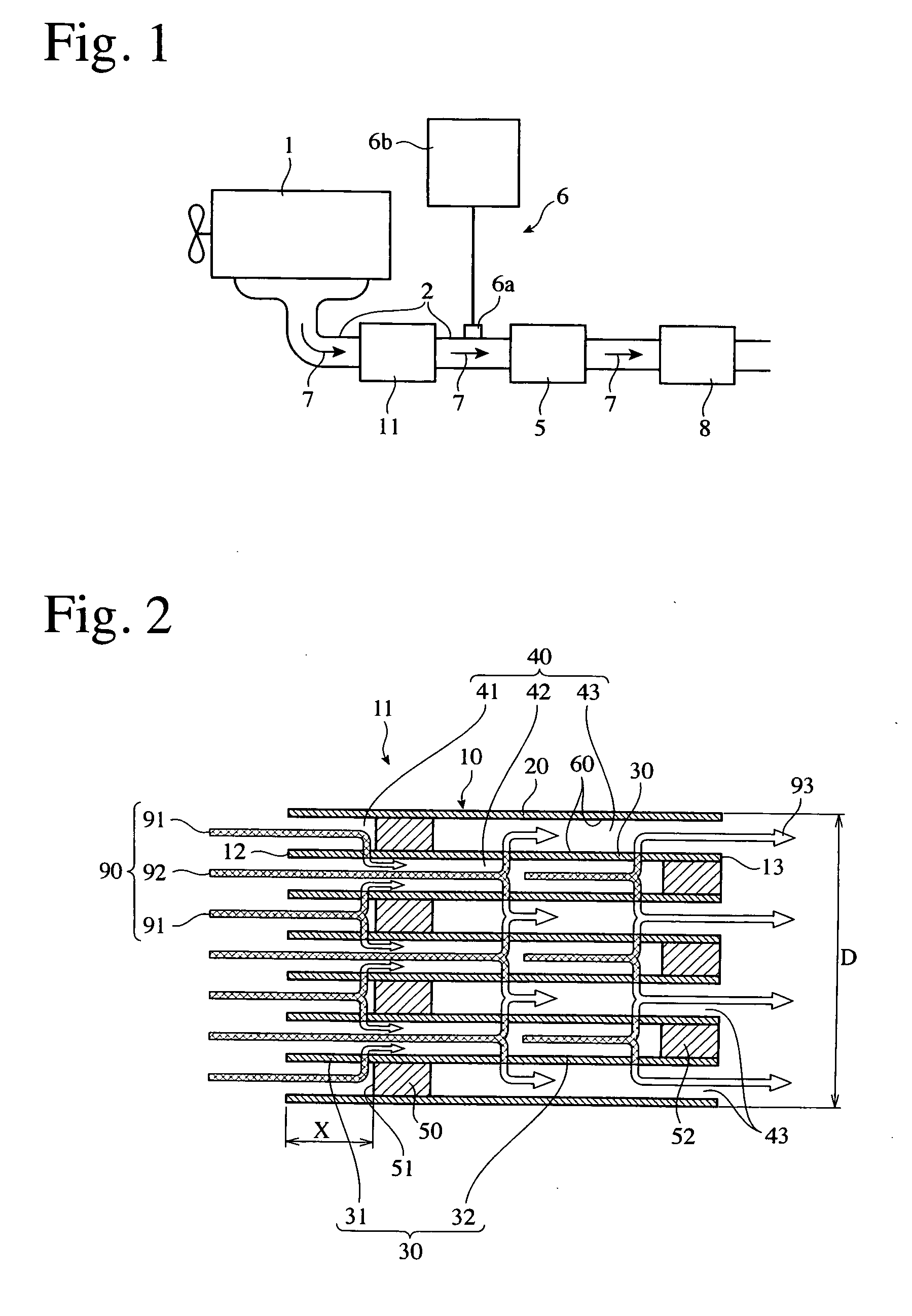
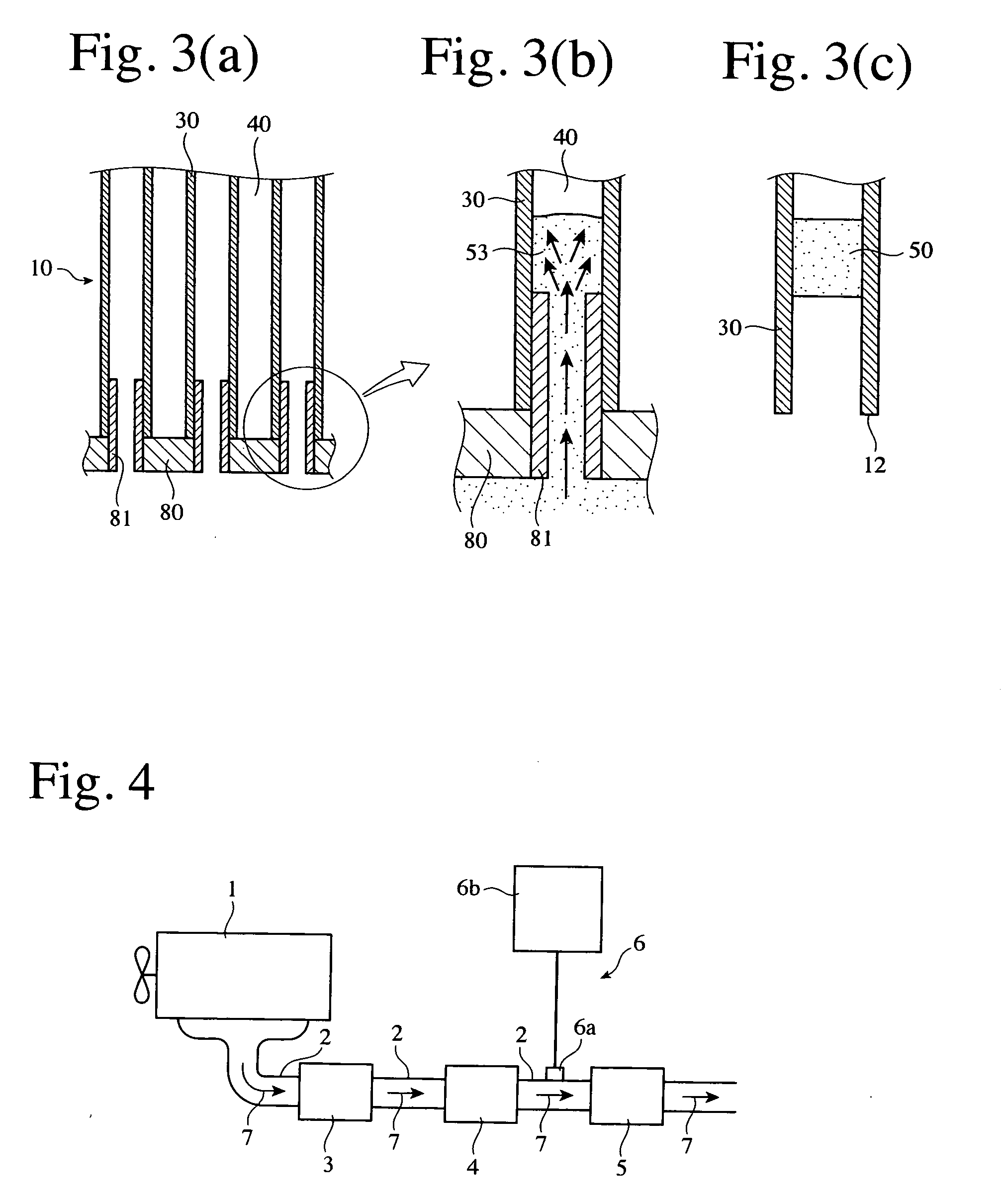
[0062] A honeycomb filter 11 for use in an exhaust gas-cleaning apparatus for a diesel engine was produced by the method shown in FIG. 3. Cordierite-forming material powder containing kaolin, talc, silica, aluminum hydroxide and alumina was mixed with a molding aid, a pore-forming agent and a predetermined amount of water, and then fully blended to prepare a ceramic material extrusion-moldable to a honeycomb structure. This ceramic material with moldable consistency was extrusion-molded to a honeycomb structure having large numbers of rectangular-cross-sectioned flow paths partitioned by porous cell walls inside a peripheral wall. The resultant green body was dried and fired to produce a ceramic honeycomb structure 10 having a diameter D of 267 mm and a length L of 305 mm, with porous cell walls 30 having thickness of 0.3 mm, a pitch of 1.50 mm, porosity of 65% and an average pore diameter of 20 μm.

[0063] As shown in FIG. 3(a), a resin mask 80 provided with slurry-introdu...

Example

COMPARATIVE EXAMPLE 1

[0066] Plugs for sealing one end of each flow path of the same ceramic honeycomb structure 10 as in Example 1 were formed in a checkerboard pattern as shown in FIG. 5 by a known method. The plugs were fired in the same manner as in Example 1, and a catalyst containing 2 g / L of Pt was supported by the porous cell walls 30 of the honeycomb structure 10. The resultant honeycomb filter 11 was disposed in an exhaust gas path 2 of a diesel engine together with a reducing agent-supplying apparatus 6, an SCR catalytic converter 5 and an ammonia slip means 8 in the same manner as in Example 1.

[0067] An exhaust gas at 200° C. was caused to flow through this exhaust gas-cleaning apparatus for 2 hours, so that PM was accumulated in the honeycomb filter 11. An exhaust gas at 350° C. and an unburned fuel were then supplied to the honeycomb filter 11, and after 5 minutes from starting the burning of PM, the temperature of the exhaust gas was lowered to 100° C., and the suppl...

Example

EXAMPLE 2 AND 3

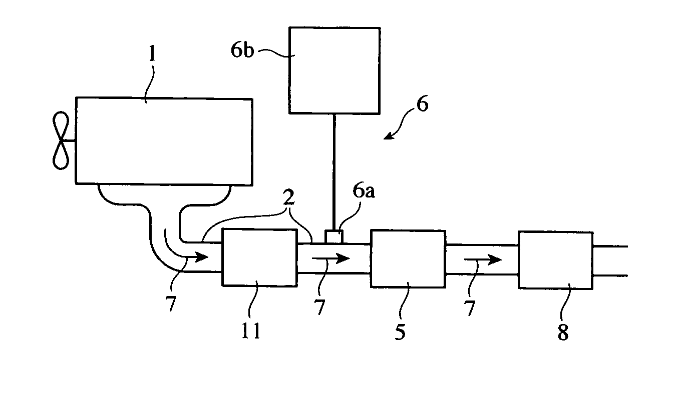
[0068] Using the same honeycomb filter 11 as in Example 1 except that the distance X was changed to 40 mm (Example 2) and 30 mm (Example 3), respectively, the exhaust gas-cleaning apparatus shown in FIG. 1 was produced. The displacement V (liter) of the diesel engine, the diameter D (mm) of the honeycomb filter, D / V, and the distance X are shown in Table 1.

[0069] An exhaust gas at 200° C. was caused to flow through the honeycomb filter in each an exhaust gas-cleaning apparatus for 2 hours, so that PM was accumulated in the honeycomb filter 11. An exhaust gas at 350° C. and an unburned fuel were then supplied to the honeycomb filter 11, and after 5 minutes from starting the burning of PM, the temperature of the exhaust gas was lowered to 100° C., and the supply of the unburned fuel was stopped. After 2 minutes passed, the temperature of the exhaust gas discharged from the honeycomb filter 11, and the conversion ratio of NOx to N2 in the SCR catalytic converter 5 were...


PUM

PropertyMeasurementUnit
Sheet carrier densityaaaaaaaaaa
Volumeaaaaaaaaaa
Volumeaaaaaaaaaa

Abstract

An apparatus for cleaning an exhaust gas containing nitrogen oxide and particulate matter and discharged from a diesel engine, wherein the apparatus comprises a porous ceramic honeycomb filter and an SCR catalytic converter in this order from upstream, wherein the honeycomb filter has pluralities of flow paths partitioned by porous cell walls and a catalyst supported by the porous cell walls, with desired flow paths sealed by plugs, and wherein at least one plug on the side of an exhaust gas inlet is separate inward from an exhaust gas inlet end. A ratio D/V of the diameter D (mm) of the honeycomb filter to the displacement V (liter) of the diesel engine is preferably 15 mm/liter or more. The honeycomb filter and an SCR catalytic converter are preferably contained in one case.

Description

FIELD OF THE INVENTION [0001] The present invention relates to an apparatus for cleaning an exhaust gas discharged from a diesel engine and containing nitrogen oxide (NOx) and particulate matter. BACKGROUND OF THE INVENTION [0002] Demand is mounting for diesel engines mainly in Europe because of their high fuel efficiency. Because particulate matter (hereinafter referred to simply as “PM”) and NOx contained in exhaust gases discharged from diesel engines largely affect human health, various investigations have been conducted to reduce the amounts of PM and NOx. As an exhaust gas-cleaning apparatus for reducing the amounts of PM and NOx in an exhaust gas, JP2000-303826 discloses, as shown in FIG. 4, an exhaust gas-cleaning apparatus comprising an oxidation catalyst 3, a filter 4 and a selective catalytic reduction (SCR) catalyst 5 in this order from upstream in an exhaust gas path 2 connected to a diesel engine 1, a valve 6a communicating with a reducing agent reservoir 6b being prov...

Claims


Application Information

Patent Timeline
IPC IPC(8): B01D53/34
CPCB01D53/9431B01D2258/012F01N3/0231F01N3/0253F01N3/035F01N3/2066F01N13/0097F01N2340/00F01N2510/0682F01N2610/02F01N2610/1453Y02T10/24F01N2250/02Y02T10/12
Inventor SUWABE, HIROHISAFUNABASHI, HIROSHI
Owner HITACHI METALS LTD
Why Eureka
Try Eureka