
Carbon monoxide transforming apparatus for fuel cell and fuel cell power generating system

a technology of transforming apparatus and fuel cell, which is applied in the direction of physical/chemical process catalysts, bulk chemical production, sustainable manufacturing/processing, etc., can solve the problems of deteriorating catalyst, shortening the life of catalyst, and not using purified hydrogen to be generally supplied to the fuel electrode in view of saving cos

Inactive Publication Date: 2007-08-16
HARADA MAKOTO +3
View PDF9 Cites 5 Cited by
  • Summary
  • Abstract
  • Description
  • Claims
  • Application Information

AI Technical Summary

Benefits of technology

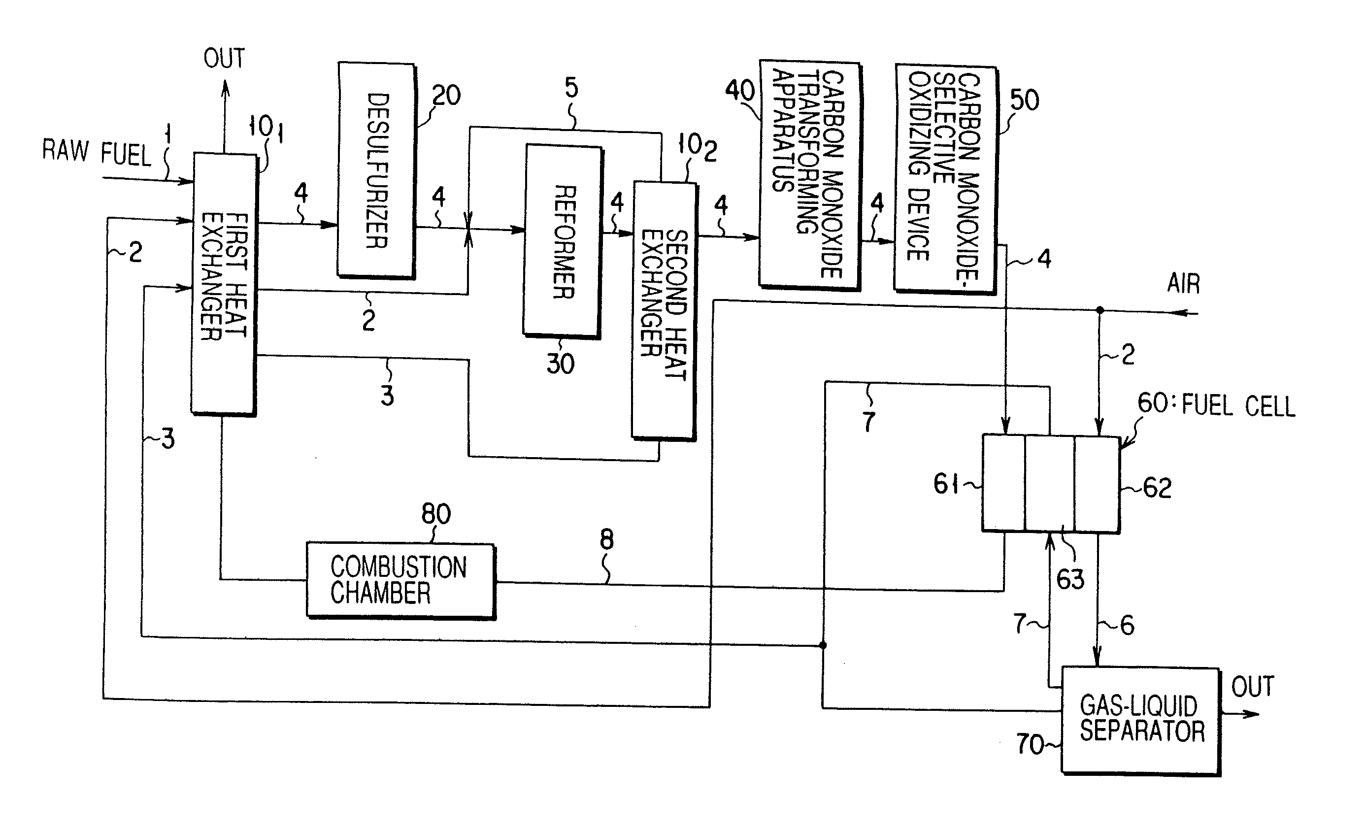
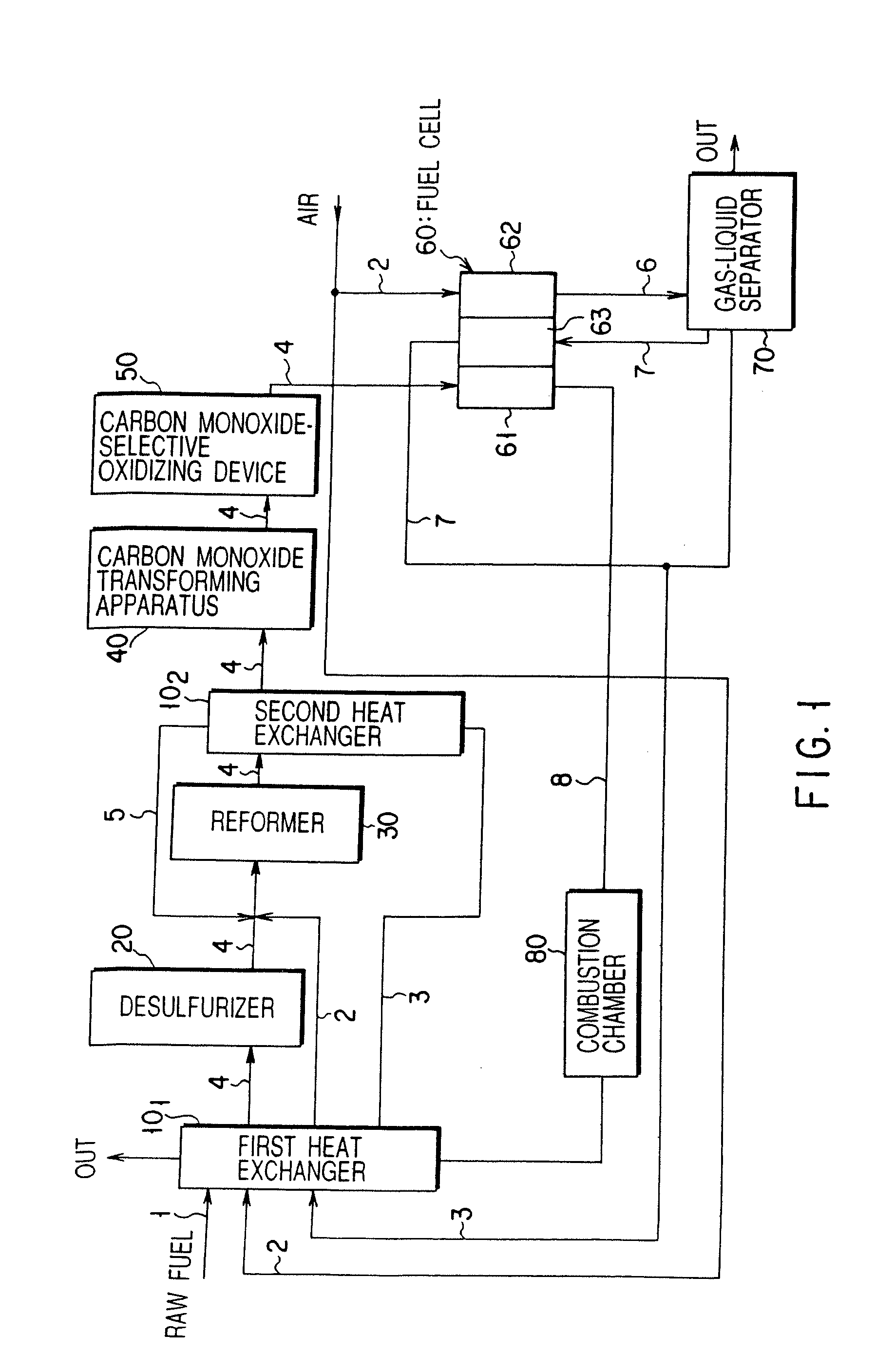
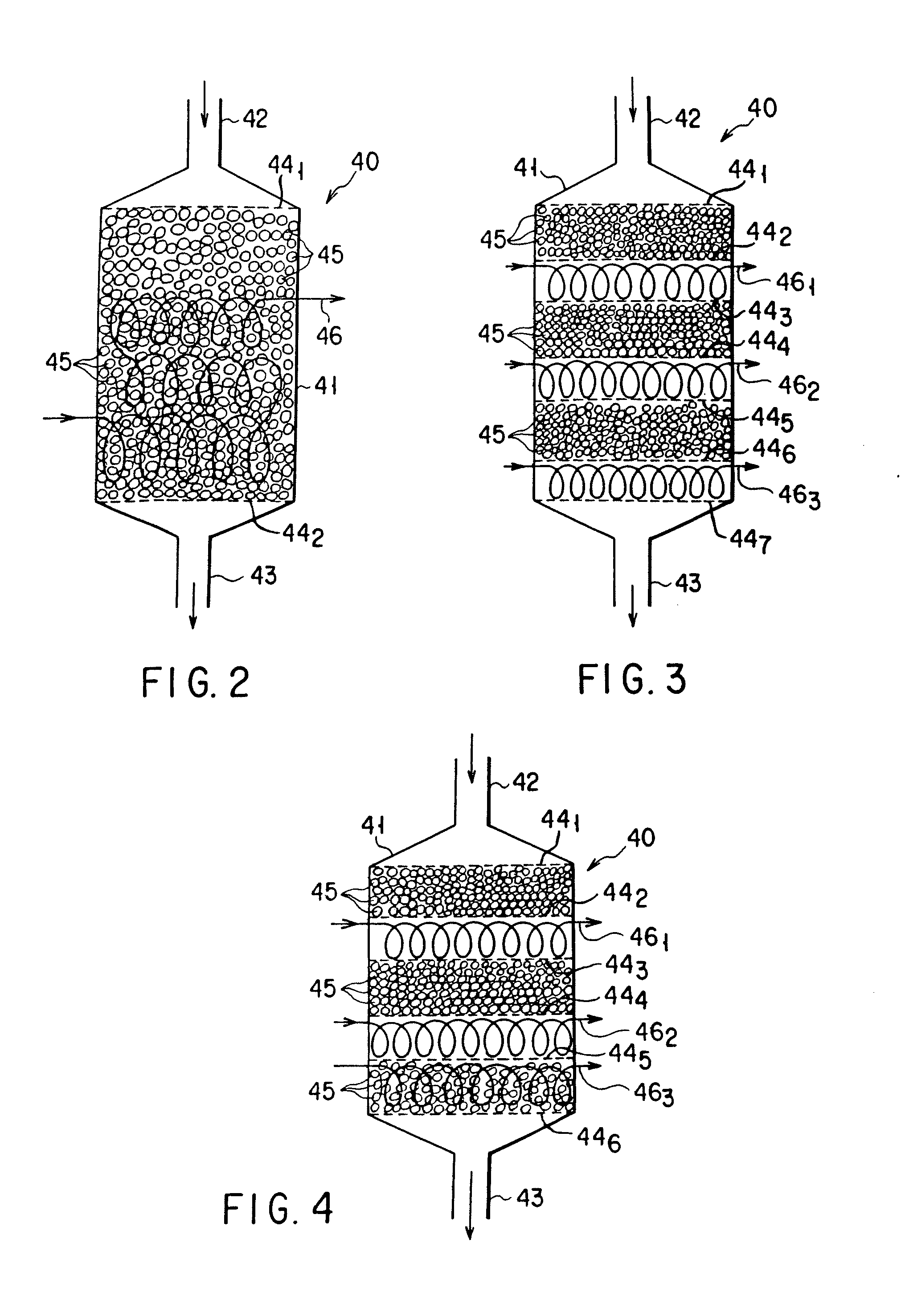
[0014] The present invention is to provide a carbon monoxide transforming apparatus for fuel cell, which is capable of instantaneously performing a transformation and start-up operation on the occasion of transforming a gas containing, as main components, hydrogen, carbon monoxide, carbon dioxide and water vapor so as to convert the carbon monoxide into carbon dioxide and at the same time to generate hydrogen, and also capable of operating it at an expanded range of temperature.
[0015] The present invention is also to provide a fuel cell power generating system provided with a transforming apparatus which is capable of instantaneously performing a transformation and start-up operation on the occasion of transforming a gas containing, as main components, hydrogen, carbon monoxide, carbon dioxide and water vapor so as to convert the carbon monoxide into carbon dioxide and at the same time to generate hydrogen, and also capable of operating it at an expanded range of temperature, thereby enabling the fuel cell power generating system to be effectively and instantaneously operated by preventing an electrochemical reaction between hydrogen and oxygen from being obstructed by the carbon monoxide.

Problems solved by technology

In this case however, pure hydrogen to be generally supplied to the fuel electrode is not used in view of saving cost.
However, due to this microstructure of the catalyst, if the catalyst is employed under a high temperature condition, the sintering of the catalyst tends to occur, thus deteriorating the catalyst.
For example, if the catalyst is used at a temperature of 270° C. or more for a long period of time, the catalytic activity of the catalyst would be deteriorated, thus shortening the life of the catalyst.
Moreover, since the fuel cell power generating system is not of closed system, the intrusion more or less of the external atmosphere into the system may be inevitably caused to take place on the occasion of stoppage.
There is also a problem in the aforementioned carbon monoxide transforming apparatus for fuel cell that since the aforementioned copper-zinc oxide-based catalyst is oxidized in air atmosphere at room temperature, the reduction of the catalyst is required at the time of start-up, thereby making it difficult to realize a quick (preferably, instantaneous) start-up, and therefore, the heat resistance of the catalyst is also required to be improved.

Method used


Image

  • Carbon monoxide transforming apparatus for fuel cell and fuel cell power generating system
  • Carbon monoxide transforming apparatus for fuel cell and fuel cell power generating system
  • Carbon monoxide transforming apparatus for fuel cell and fuel cell power generating system

Examples


example 1

[0085] First of all, titanium oxide powder and a hydrocarbon (binder) (both available in the market) were introduced into a granulating machine to granulate the mixture into a spherical porous body having a diameter of 3 to 4 mm, thereby manufacturing a carrier. Then, a predetermined quantity of aqueous solution of platinic chloride was impregnated into the aforementioned carrier, dried at a temperature of about 120° C., and sintered in air atmosphere at a temperature of 500° C. Thereafter, the resultant body was subjected to a reduction treatment for 4 hours in a reducing atmosphere containing hydrogen at a temperature of 400° C., thereby manufacturing a catalyst (Pt / TiO2-based catalyst) having a composition shown in the following Table 1.

example 2

[0086] First of all, a titanium oxide carrier manufactured in the same manner as in Example 1 was impregnated with a predetermined quantity of aqueous solution of cerium nitrate and then with a predetermined quantity of aqueous solution of platinic chloride. The resultant body was then dried at a temperature of about 120° C., and sintered in air atmosphere at a temperature of 500° C. Thereafter, the resultant body was subjected to a reduction treatment for 4 hours in a reducing atmosphere containing hydrogen at a temperature of 400° C., thereby manufacturing a catalyst (P—CeO2 / TiO2-based catalyst) having a composition shown in the following Table 1.

examples 3 and 4

[0087] First of all, a titanium oxide carrier manufactured in the same manner as in Example 1 was impregnated with a predetermined quantity of aqueous solution of cerium nitrate, with a predetermined quantity of aqueous solution of lanthanum nitrate, and with a predetermined quantity of aqueous solution of platinic chloride in the mentioned order. The resultant body was then dried at a temperature of about 120° C., and sintered in air atmosphere at a temperature of 500° C. Thereafter, the resultant body was subjected to a reduction treatment for 4 hours in a reducing atmosphere containing hydrogen at a temperature of 400° C., thereby manufacturing two kinds of catalysts (Pt—CeO2—La2O3 / TiO2-based catalyst) having a composition shown in the following Table 1.


PUM

PropertyMeasurementUnit
Percent by massaaaaaaaaaa

Abstract

A carbon monoxide transforming apparatus for fuel cell is constructed such that a catalyst having at least platinum or palladium carried on a carrier which has a base point on the surface thereof is filled in a reaction vessel having gas inlet and outlet ports. As a result, a transformation and start-up operation can be instantaneously performed on the occasion of transforming a gas containing, as main components, hydrogen, carbon monoxide, carbon dioxide and water vapor so as to convert the carbon monoxide into carbon dioxide and at the same time to generate hydrogen. Additionally, the operating temperature for the transformation can be expanded.

Description

CROSS REFERENCE TO RELATED APPLICATIONS [0001] This is a Continuation of Application No. PCT / JP00 / 00716, filed Feb. 9, 2000. [0002] This application is based upon and claims the benefit of priority from the prior Japanese Patent Application No. 11-032454, filed Feb. 10, 1999, the entire contents of which are incorporated herein by reference. BACKGROUND OF THE INVENTION [0003] This invention relates to a carbon monoxide transforming apparatus for fuel cell, and to a fuel cell power generating system incorporated with the transforming apparatus. [0004] In recent years, a fuel cell such as a phosphoric acid type fuel cell, a solid polymer type fuel cell, etc. has been put to practical use and is still being studied and developed. This fuel cell is designed such that hydrogen (or a gas containing hydrogen) is supplied to a fuel electrode, and oxygen (a gas containing oxygen such for example as air) is supplied to an oxidizing electrode to allow an electrochemical reaction to take place ...

Claims


Application Information

Patent Timeline
IPC IPC(8): H01M8/06B01J8/02B01J8/04B01J21/06B01J23/06B01J23/42B01J23/44B01J23/60B01J23/63B01J23/745B01J23/80B01J23/89B01J37/00B01J37/02C01B3/16C01B3/58H01M8/04H01M8/10
CPCB01J8/0453Y02E60/50B01J21/06B01J21/063B01J23/06B01J23/42B01J23/44B01J23/60B01J23/63B01J23/745B01J23/80B01J23/894B01J37/0063B01J37/0205B01J2208/00141B01J2208/00203B01J2208/00884B01J2219/00006C01B3/16C01B3/38C01B3/48C01B3/583C01B2203/0233C01B2203/0261C01B2203/0283C01B2203/0294C01B2203/044C01B2203/047C01B2203/066C01B2203/0811C01B2203/0822C01B2203/0827C01B2203/0883C01B2203/1058C01B2203/1064C01B2203/107C01B2203/1082C01B2203/127C01B2203/146H01M8/04029H01M8/04097H01M8/0618H01M8/0662H01M8/0668H01M8/0675H01M2008/1095B01J8/0496Y02P20/52Y02P20/10
Inventor HARADA, MAKOTOYOSHINO, MASATOWADA, KATSUYAKOETSUKA, JUNJI
Owner HARADA MAKOTO
Learn More