Phase locked loop circuitry

a loop filter and phase lock technology, applied in the direction of phase difference detection angle demodulation, automatic control of pulses, electrical equipment, etc., can solve the problems of requiring a substantial chip area, tedious and time-consuming to trim a loop filter to the required application, and generally needing a large filter capacitor. , to achieve the effect of reducing space requirements, simplifying manufacturing, and easy manipulation

Inactive Publication Date: 2007-08-23
APPLE INC
View PDF6 Cites 24 Cited by
  • Summary
  • Abstract
  • Description
  • Claims
  • Application Information

AI Technical Summary

Benefits of technology

[0008] The invention is directed to a phase locked loop circuit having an improved filter section with reduced space requirements and having a layout enabling simplified manufacturing thereof, thereby overcoming or at least alleviating the shortcomings of the prior art. In one embodiment the invention comprises a flexible and easily manipulated phase locked loop circuit that is easily adjusted for use in any application.
[0009] In accordance with the invention a phase locked loop circuit is provided comprising a phase detector receiving as input a reference signal and an oscillator signal and detecting a phase difference between them and thereafter outputting a phase error signal based on the detected phase difference. The circuit further comprises a loop filter section connected to the phase detector and used for filtering the input error signal. The loop filter section is in turn connected to a voltage controlled oscillator, the output of which is fed back into the phase detector. In one embodiment, the loop filter section comprises a digital loop filter section comprising digital filtering means and a digital to analog converter. The loop filter of the phase-locked loop circuit is thus implemented digitally in one embodiment instead of using traditional analog components. The chip area required for such a digital loop filter is substantially smaller than an analog equivalent and can be implemented on a single integrated circuit die together with an oscillator, phase detector and possible counters. There is thus no need for the use of external components, greatly simplifying the design and manufacture of the circuit, and having reduced assembly costs. Further, by means of the digital filter the loop dynamics are also easily changed.
[0010] In accordance with one embodiment of the invention the loop filter section of the circuit further comprises an analog to digital converter connected between the phase detector and the digital filtering means. A variable solution is thus provided, enabling the use of a digital or analog phase-detector and giving the designer flexibility to choose devices best suited for a certain application.

Problems solved by technology

Such loop filter capacitors generally need to be rather large and require therefore a substantial area on the chip.
There are several drawbacks related to such loop filters.
Analog components have some tolerances and it is often tedious and time consuming to trim a loop filter to the required application, entailing for example measurements of the loop filter response and calibration of the frequency modulated signal.

Method used


Image

  • Phase locked loop circuitry
  • Phase locked loop circuitry
  • Phase locked loop circuitry

Examples


first embodiment

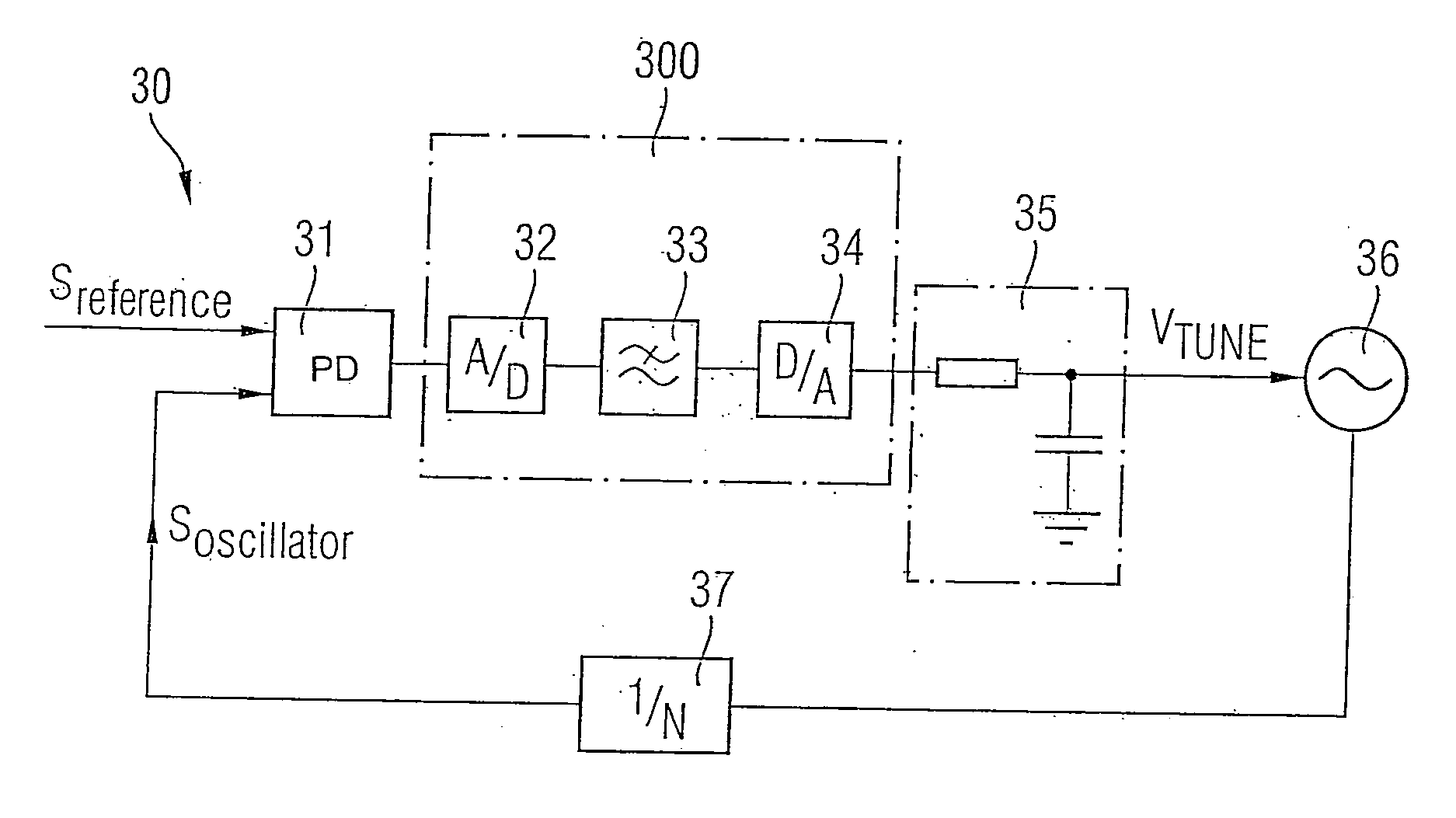
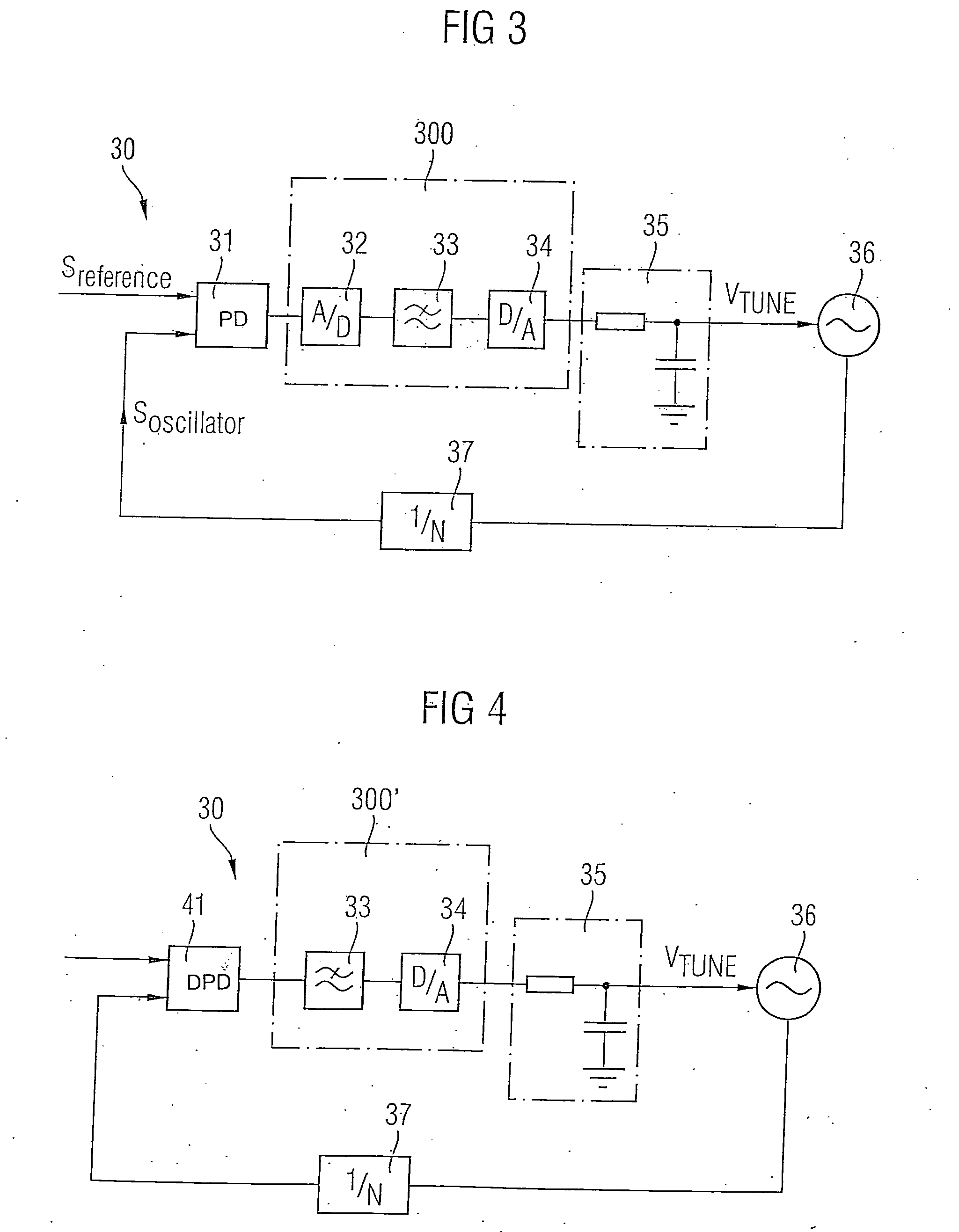
[0024] the present invention is described with reference to FIG. 3. A phase locked loop 30 in accordance with one embodiment of the invention comprises a phase detector (PD) 31 for receiving as inputs a reference signal Sreference and an oscillator signal Soscillator and measuring the phase difference therebetween. In one embodiment a divider 37 is provided after the voltage controlled oscillator 36 for enabling a dividing of the oscillator signal Soscillator. The phase difference detection can be performed in any suitable way, for example, by measuring the time between positive edges of the two signals. In the embodiment shown in FIG. 3, the phase detector 31 is analog and thus outputs an analog error signal Serror. However, the phase detector 31 can alternatively output a digital output, and it can, for example, be implemented by means of an exclusive OR (XOR) gate, which maintains a 90° phase difference or it can be implemented by means of a simple state machine determining which...


PUM


Abstract

The invention relates to a phase-locked loop circuit including a phase detector, loop filter and an oscillator. The loop filter is implemented digitally instead of by means of analog components. The chip area required for such a digital loop filter is substantially smaller than an analog equivalence and can be implemented on a single integrated circuit die together with an oscillator, phase detector and possible counters. There is thus no need for the use of external components, greatly simplifying the design and manufacture of the circuit, and having reduced assemblage costs. Further, by means of the digital filter the loop dynamics are also easily changed.

Description

REFERENCE TO RELATED APPLICATIONS [0001] This application claims the benefit of the priority date of European application EP 06 001 886.8, filed on Jan. 30, 2006, the contents of which are herein incorporated by reference in their entirety. FIELD OF THE INVENTION [0002] The invention generally relates to phase locked loop circuitry and to a method for controlling an oscillator in such circuitry. BACKGROUND OF THE INVENTION [0003] A phase locked loop (PLL) is a closed-loop feedback control system maintaining a generated signal in a fixed phase relationship to a reference signal, and is widely used in electronic devices, such as radio receivers and transmitters. FIG. 1 is a block diagram illustrating schematically the different parts of a typical PLL. The PLL 1 generally comprises a phase detector 2, a filter section 3 and a voltage-controlled oscillator (VCO) 4. There may further be a divider 5 or a divide-by-N counter in the feedback path in order to make the output of the PLL a mul...

Claims


Application Information

Patent Timeline
Patent Type & Authority Applications(United States)
IPC IPC(8): H03D3/24
CPCH03L7/093
Inventor LANDMARK, JOAKIM
Owner APPLE INC
Why Eureka
Try Eureka