Process of gas treatment to remove pollutants
a gas treatment and pollutant technology, applied in the direction of separation processes, hydrogen sulfides, sulfur compounds, etc., can solve the problems of high capital and operating costs, insufficient reduction of pollutants from a gas, and low sulfur content of flue gas
- Summary
- Abstract
- Description
- Claims
- Application Information
AI Technical Summary
Benefits of technology
Problems solved by technology
Method used
Image

Examples
example 1
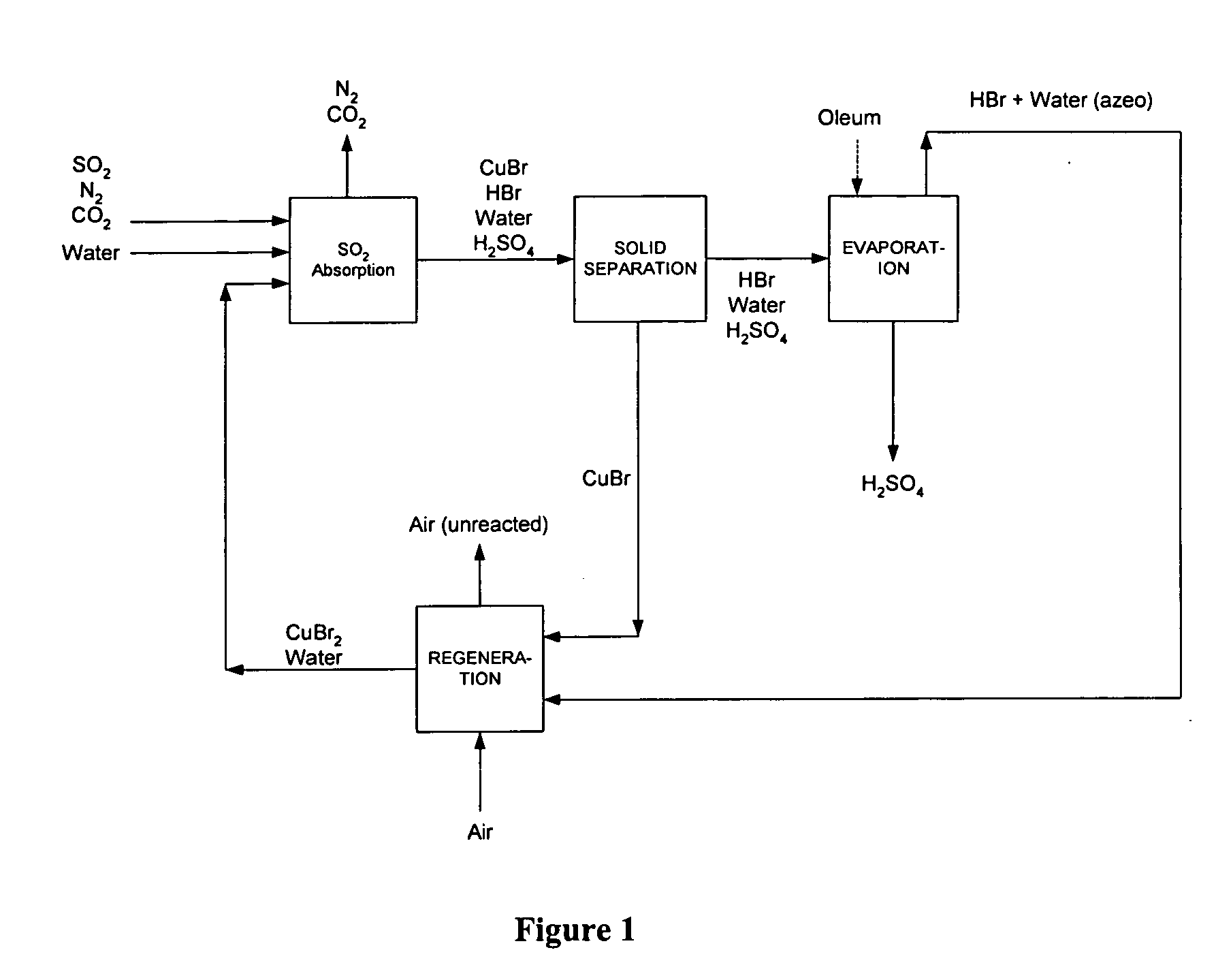
[0074] A solution was prepared by dissolving 8 g of CuBr2 (anhydrous) in 50 ml DI water at room temperature. The starting CuBr2 solution was an emerald green color. Pure SO2 gas, from a lecture bottle (Aldrich), was bubbled through the aqueous CuBr2 solution at a flow rate of 1.5 cm3 / min. A white crystalline precipitate of CuBr formed continuously, along with discoloration of the solution, as the Cu was removed as a CuBr precipitate. The reaction was conducted at room temperature and atmospheric pressure. The SO2 was reacted until the solution became colorless (i.e., complete CuBr2 consumption). The CuBr2 was then regenerated by oxidizing the CuBr precipitate. In particular, 1 g of the CuBr precipitate was suspended in a solution of 2 ml HBr (48%) and 20 ml DI water. The solution was purged with oxygen at a flow rate of 1 cm3 / min for 8 hours, at room temperature and atmospheric pressure. A complete transfer of the insoluble CuBr to the water soluble CuBr2 occurred within 6 hours.
example 2
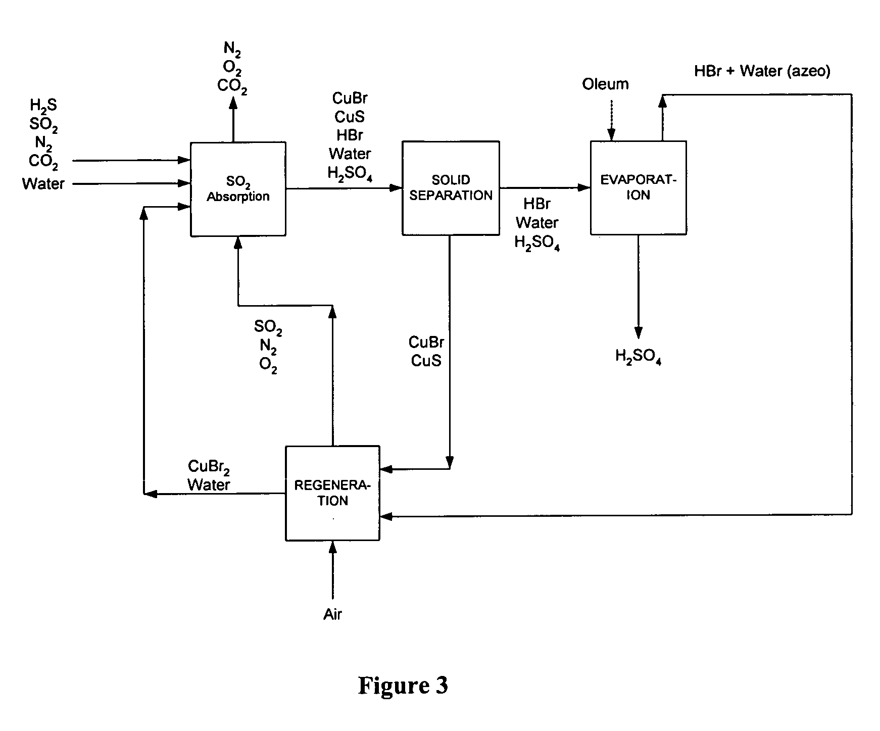
[0075] Using the process of the present invention, a flue gas stream generated by a copper smelting process may be treated using a process scheme similar to that depicted in FIG. 3. The flue gas stream has a flow rate of 100,000 m3 / hr and contained nitrogen, carbon dioxide and oxygen, with mole fractions of 0.9, 0.08, and 0.12, respectively. The flue gas also contains 1000 ppm SO2 and 100 ppm H2S. The mercury content of the gas is 2 g / hr.
[0076] The reaction of SO2 is carried out in a 10 m3 reactor at 25° C. and 5 bar using an aqueous solution of 30% by weight CuBr2. Regeneration of the cataloreactant is carried out at 25° C. and 5 bar, in a reactor with a volume of 8 m3. The air flow rate in the regeneration reactor is 1000 m3 / hr. The SO2 content in the treated gas outlet was reduced to approximately 100 ppm, and the H2S content in the treated gas was reduced to 10 ppm. The process generated 400 kg / hr of sulfuric acid. Mercury was removed to below the detection limits, and the accu...
example 3
[0077] Using the process of the present invention, a biogas stream with a flow rate of 30,000 m3 / day and containing 60% methane, 39% carbon dioxide and 1% hydrogen sulfide was treated. The biogas stream is bubbled into an aqueous solution containing 30% by weight copper (II) bromide at ambient temperature and atmospheric pressure. Using a process scheme similar to that depicted in FIG. 3, the hydrogen sulfide present in the biogas is converted to a copper sulfide precipitate in an absorption reactor with a volume of 6 m3. Copper (I) bromide is also formed as a precipitate and removed from the aqueous mixture together with copper sulfide using a hydrocyclone. The solids were transferred to a 5 m3 regeneration reactor and copper (II) bromide is regenerated by bubbling air into the aqueous slurry. The regeneration is performed at ambient temperature and pressure. Sulfur dioxide formed during regeneration is recycled into the SO2 absorption reactor. The outlet gas from the absorption re...
PUM
| Property | Measurement | Unit |
|---|---|---|
| temperature | aaaaa | aaaaa |
| temperature | aaaaa | aaaaa |
| pressure | aaaaa | aaaaa |
Abstract
Description
Claims
Application Information
 - R&D
- Intellectual Property
- Life Sciences
- Materials
- Tech Scout
- Unparalleled Data Quality
- Higher Quality Content
- 60% Fewer Hallucinations
Browse by: Latest US Patents, China's latest patents, Technical Efficacy Thesaurus, Application Domain, Technology Topic, Popular Technical Reports.
© 2025 PatSnap. All rights reserved.Legal|Privacy policy|Modern Slavery Act Transparency Statement|Sitemap|About US| Contact US: help@patsnap.com