This helps you quickly interpret patents by identifying the three key elements:
Problems solved by technology
Method used
Benefits of technology
Benefits of technology
[0053]The structure of the power electronics equipment described above facilitates forming the primary and secondary windings by etching an electrical conductor, shortening the winding diameters of the primary and secondary windings, and narrowing the spacing between the primary and secondary windings. Therefore, the coupling coefficient of the primary and secondary windings is improved, the area, in which the magnetic flux intersects the primary and secondary windings, is narrowed, and the adverse effects of the noises caused by the external magnetic flux are reduced.
[0080]As described above, the power electronics equipment includes insulating transformers formed by micro-machining techniques and facilitates increasing the coupling coefficient of the primary and secondary windings, narrowing the area, in which the magnetic flux intersects the primary and secondary windings, reducing the adverse effects of the noises caused by external magnetic fluxes, suppressing the deterioration by aging, and improving the resistance thereof against hazardous environments.
Problems solved by technology
However, because it is necessary, for the method that employs photocouplers as the means for insulating the transmitted signals, to consider (1) the temperature characteristics of the current amplification factor hfe of a transistor, (2) the deterioration by aging of the light emission efficiency of a light emitting diode, and (3) the variations of the CTR, it is difficult to design a circuit that can be used continuously over 10 years in vehicles, industrial equipments and such high temperature environments.
The use of a cored transformer as an insulating transformer for signal transmission is affected adversely by the temperature dependence of the magnetic permeability of a magnetic core material, the high temperature dependence of the coupling coefficient, and the difficulties in reducing the costs and dimensions of the apparatus.
Therefore, the circuit scale is inevitably large.
However, since the magnetic circuit is not closed, external magnetic fluxes are liable to be superimposed as noise onto the secondary winding, causing malfunctions.
Method used
Image
Click on the blue label to locate the original text in one second.
Reading with bidirectional positioning of images and text.
Examples
first embodiment
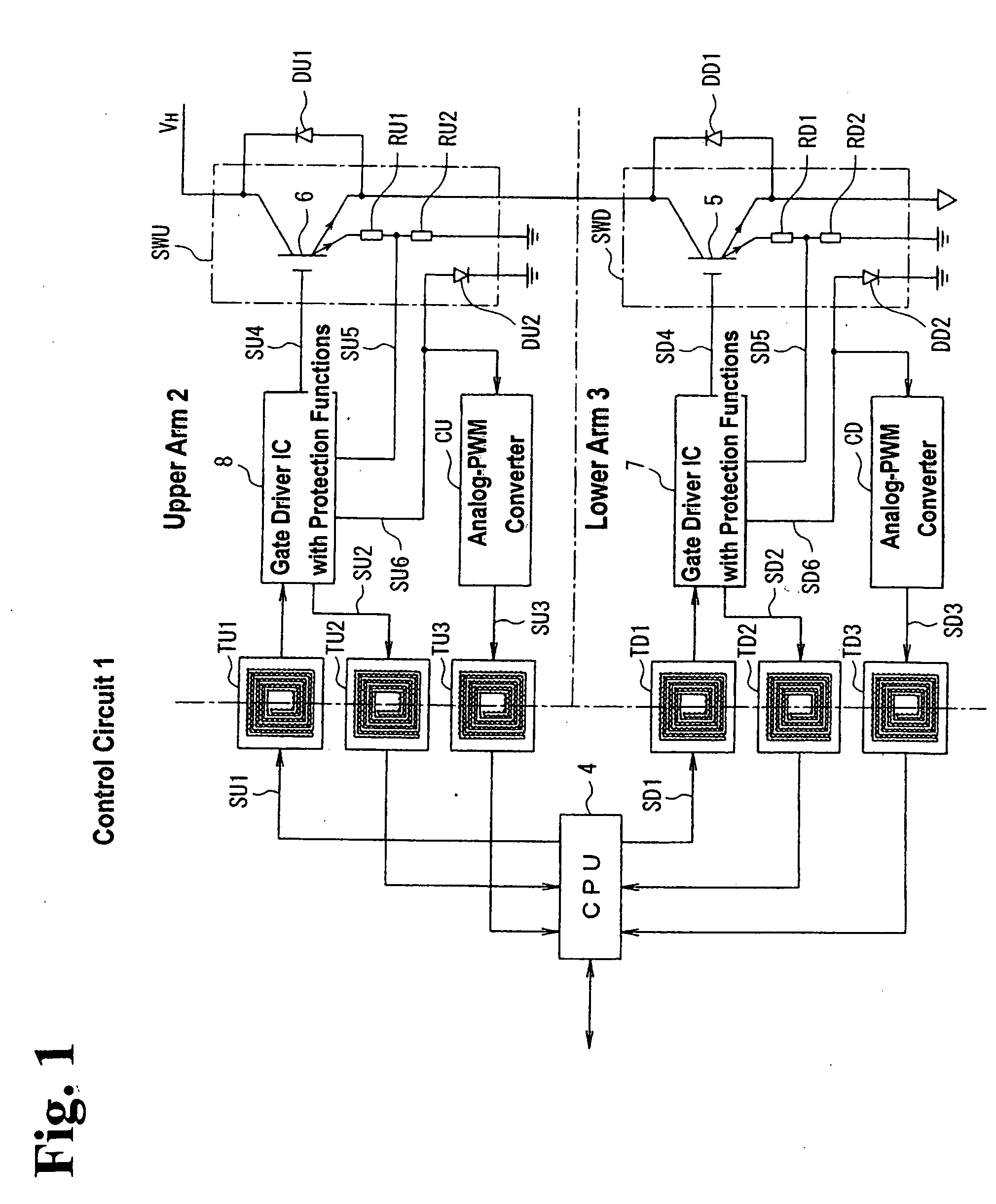
[0102]FIG. 1 is a block diagram schematically showing an intelligent power module for a step-up and step-down converter, to which power electronics equipment according to the invention is applied.
[0103]Referring now to FIG. 1, the intelligent power module for the step-up and step-down converter according to the first embodiment includes a switching device SWU for an upper arm and a switching device SWD for a lower arm that directs a current flow to the load and interrupts the current flowing to the load, and a control circuit 1 that generates control signals directing the conduction and non-conduction of switching devices SWU and SWD. Control circuit 1 may be comprised of a CPU 4 or a logic IC, or a system LSI that mounts a logic IC and a CPU thereon.
[0104]Switching devices SWU and SWD are connected in series so that switching devices SWU and SWD may work for upper arm 2 and for lower arm 3, respectively. An IGBT 6 that conducts switching operations in response to a gate signal SU4 ...
second embodiment
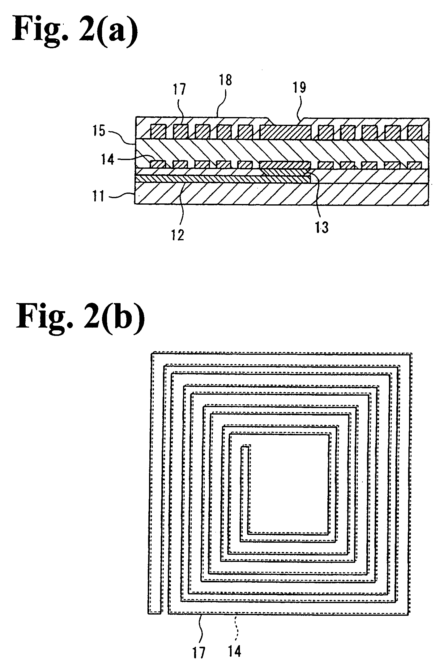
[0127]FIGS. 4(a) through 4(l) and FIGS. 5(a) through 5(h) are cross sectional views describing the manufacturing method according to the invention for manufacturing an insulating transformer.
[0128]Referring now to FIG. 4(a), a leading diffusion 52 for leading out a primary coil pattern 55a from the center thereof is formed in a semiconductor substrate 51 by selectively implanting As, P, B and another such impurity into semiconductor substrate 51. The material for semiconductor substrate 51 is selected from Si, Ge, SiGe, SiC, SiSn, PbS, GaAs, InP, GaP, GaN, and ZnSe.
[0129]Referring now to FIG. 4(b), an insulator layer 53 is formed by plasma CVD and other such methods on semiconductor substrate 51, in which leading diffusion 52 is formed. For example, a siliconoxide film or a siliconnitride film may be used for insulator layer 53.
[0130]Referring now to FIG. 4(c), a resist pattern 54, in which an opening 54a is formed corresponding to the leading port for leading out primary coil pat...
third embodiment
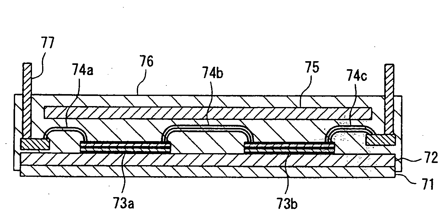
[0148]FIG. 6 is a cross sectional view showing the mounted state of an intelligent power module for the step-up and step-down converter according to the invention.
[0149]Referring now to FIG. 6, an IGBT chip 73a and an FWD chip 73b are mounted on a copper base board 71 for heat dissipation via a ceramics substrate 72 for insulation. IGBT chip 73a and FWD chip 73b are connected to each other, and to a main terminal 77 for taking out the main circuit current, via bonding wires 74a through 74c. A circuit board 75 for driving the IGBT's gate and for monitoring the IGBT is arranged above IGBT chip 73a and FWD chip 73b. IGBT chip 73a, FWD chip 73b, and circuit board 75 are sealed with a mold resin 76. IGBT chip 73a and FWD chip 73b constitute switching devices, which make a current flow to the load and interrupt the current flowing to the load, such that the switching devices for the upper and lower arms are connected in series to each other. A control circuit that generates control signal...
PUM
Abstract
Power electronics equipment includes air-cored insulating transformers inserted between a control circuit grounded to a vehicle body and an upper arm biased at a high voltage, and air-cored insulating transformers between the control circuit grounded to the vehicle body and the lower arm biased at a high voltage. Each of the air-cored insulating transformers includes a primary winding and a secondary facing to each other. The power electronics equipment facilitates improving resistance against hazardous environments, suppressing the deterioration by aging, reducing the adverse effects of noise caused by external magnetic flux, and transmitting and receiving signals while insulating the low and high voltage sides electrically from each other.
Description
BACKGROUND OF THE INVENTION AND RELATED ART STATEMENT[0001]The present invention relates to power electronics equipment. Specifically, the present invention relates to power electronics equipment well suited for transmitting signals to switching devices via insulating transformers.[0002]Vehicle equipment is mounted with a step-up and step-down converter and an inverter on the driving system of a motor that generates driving power for improving conversion efficiency and for reducing energy consumption.[0003]FIG. 11 is a block diagram schematically showing a vehicle drivingsystem that employs a conventional step-up and step-down converter.[0004]Referring now to FIG. 11, the vehicle drivingsystem includes a power supply 1101 that feeds electric power to a step-up and step-down converter 1102 that boosts and steps down a voltage, an inverter 1103 that converts the voltage outputted from step-up and step-down converter 1102 to the components of a three-phase voltage, and a motor 1104 t...
Claims
Application Information
Patent Timeline
Application Date:The date an application was filed.
Publication Date:The date a patent or application was officially published.
First Publication Date:The earliest publication date of a patent with the same application number.
Issue Date:Publication date of the patent grant document.
PCT Entry Date:The Entry date of PCT National Phase.
Estimated Expiry Date:The statutory expiry date of a patent right according to the Patent Law, and it is the longest term of protection that the patent right can achieve without the termination of the patent right due to other reasons(Term extension factor has been taken into account ).
Invalid Date:Actual expiry date is based on effective date or publication date of legal transaction data of invalid patent.

