Analysis method and analysis apparatus

a technology of analysis apparatus and analysis method, which is applied in the direction of optical radiation measurement, instruments, spectrometry/spectrophotometry/monochromators, etc., can solve the problems of unfavorable uniform distribution, difficult handling of reagents, and high cost of reagents, and achieves simple and economical, high reproducibility, and high accuracy

Inactive Publication Date: 2007-10-04
CANON KK
View PDF25 Cites 71 Cited by
  • Summary
  • Abstract
  • Description
  • Claims
  • Application Information

AI Technical Summary

Benefits of technology

[0017]However, as shown in FIG. 15, in the case of a porous material 161 containing a fibrous structure, the liquid analyte becomes nonuniformly distributed as indicated by reference numeral 162 and becomes elliptical. Here, a liquid analyte was dropped as a droplet on a porous material containing a fibrous structure, such as nitrocellulose, cellulose, glass fiber, and quartz fiber, and an investigation was carried out as shown in Table 1 of FIGS. 17A and 17B. As a result, it was found that the extent of the nonuniformity is 1.11 or more in terms of the value (eccentricity) obtained by (major axis length)÷(minor axis length) of the elliptic distribution. On the other hand, as similarly shown in Table 1, in the case of a non-fibrous, isotropic porous material such as polypropylene, polysulfone, polyethersulfone, or nylon, the above-mentioned eccentricity is less than 1.11. Therefore, this can bring about a more uniform distribution and is desirable.
[0022]In summary, it has been seen that compared to a porous material containing a fibrous structure such as cellulose, a non-fibrous, isotropic porous material that contains at least one of polypropylene, polysulfone, nylon and polyethersulfone, which are exemplified as being desirable, is such that as described below. That is, it has been seen that the non-fibrous, isotropic porous material permits measurements in a wide region (a band with high amplitude transmittance is relatively wide) for a terahertz wave and that the signal noise ratio is high.
[0023]It is considered that the use of a material having a high amplitude transmittance for a terahertz wave is desirable so long as the material is a non-fibrous, isotropic porous material even when the material is other than polypropylene, polysulfone, nylon, and polyethersulfone, which are enumerated above. That is, it is considered that the same effect can be expected also when employing those other materials having a relatively high amplitude transmittance and a high degree of constancy of amplitude transmittance with respect to frequency, for example, those containing at least one of Teflon (registered trademark), polyolefin, polyethylene, polystyrene, ethylene tetrafluoride resins, which have small losses for a terahertz band.
[0026]In the analysis method and analysis apparatus of the present invention, it is possible to perform analysis of a substance and to obtain information on the substance without allowing a reagent for a color reaction to be previously carried by a carrier. Therefore, it is possible to provide an analysis method and an analysis apparatus that are simple and economical. Furthermore, in the analysis method and analysis apparatus of the present invention, a non-fibrous, isotropic porous material that uses the material as described above is used and, therefore, it is possible to provide an analysis method and an analysis apparatus that have higher accuracy and higher reproducibility.

Problems solved by technology

Further, in some cases a reagent is expensive and some kinds of reagents are difficult to handle because of their toxicity.
Moreover, in the technique disclosed in Japanese Patent Application Laid-Open No. 2005-517925, a solution that serves as an analyte does no soak uniformly and nonuniform distribution is liable to be caused.
Such nonuniform distribution of the analyte gives spatial nonuniformity to the transmitted terahertz wave and may sometimes exert an adverse effect, such as noise, on the frequency region when the time waveform of the transmitted terahertz wave is Fourier transformed, which is undesirable for accurate measurement.
In addition, the amplitude transmittance of cellulose nitrate filter paper for a terahertz wave of a frequency of 2.0 THz or more is low and the amplitude transmittance has a frequency dependence, which may have an adverse effect on the accuracy of measurement.

Method used


Image

  • Analysis method and analysis apparatus
  • Analysis method and analysis apparatus
  • Analysis method and analysis apparatus

Examples


example 2

[0086]Example 2 will be described. In Example 2, as shown in FIG. 6, femtosecond pulse laser light emitted from a mode-lock titanium-sapphire laser (femtosecond laser) 71 is split into two beams by a half mirror and the like, and one bean is condensed and irradiated on a terahertz wave generator 73. A so-called photoconductive antenna that is constituted, for example, by a pair of electrodes formed on low-temperature grown gallium arsenide is used as the terahertz wave generator 73. At this time, a voltage of about 10V is applied to the photoconductive antenna.

[0087]The other beam of the femtosecond laser light split by the half mirror and the like passes through a delay optical system 72 and is then condensed and irradiated on a terahertz wave detector 74. A so-called photoconductive antenna that is similar to the terahertz wave generator 73 and is constituted by a pair of electrodes formed on low-temperature grown gallium arsenide is used as the terahertz wave detector 74. At this...

example 3

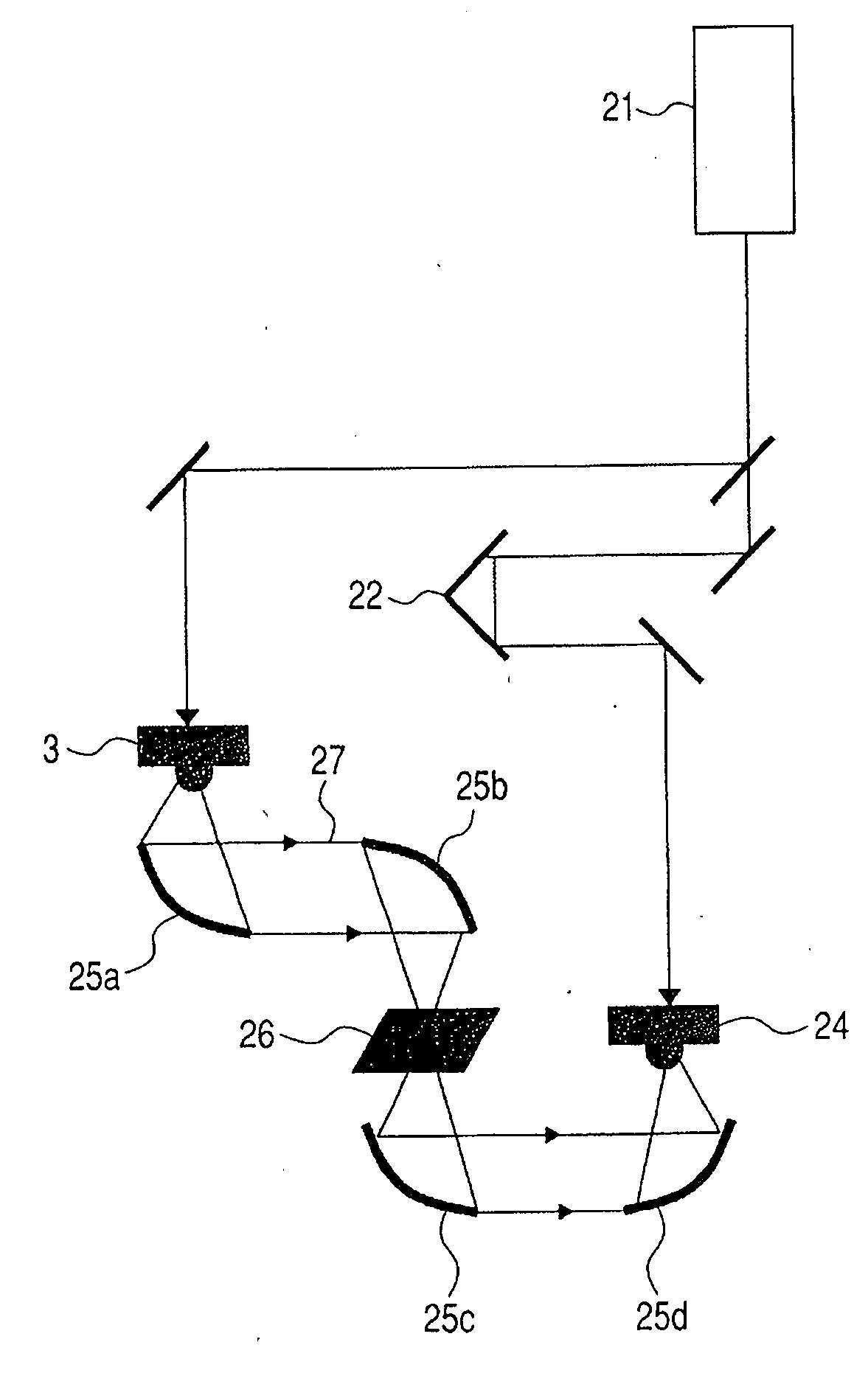
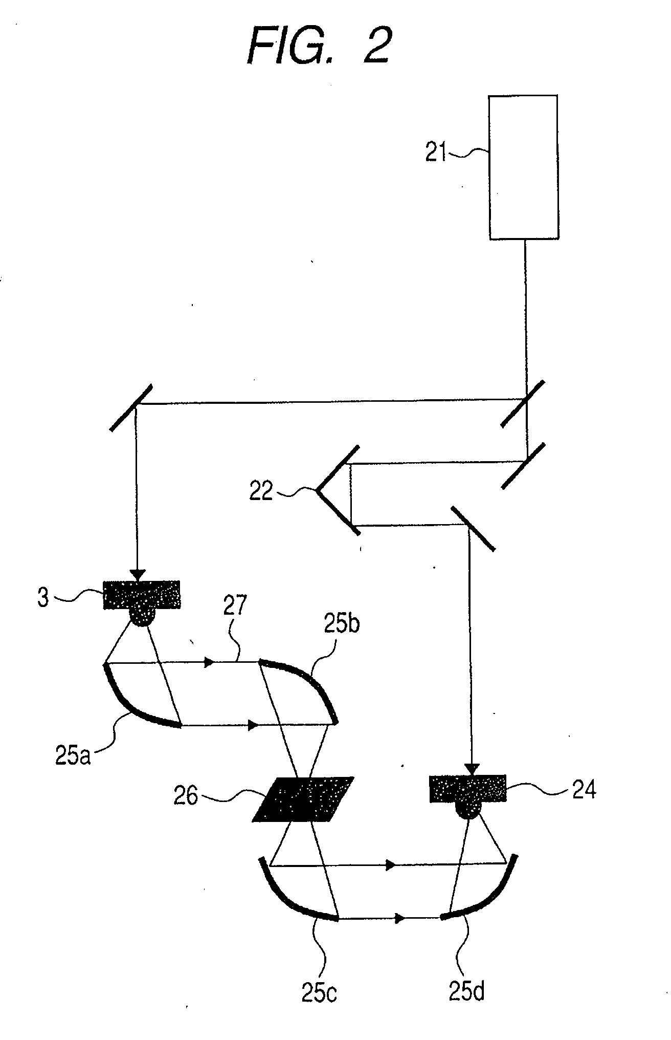
[0090]Example 3 will be described. In Example 3, as shown in FIG. 7, there is provided a mechanical XY stage 85 for driving, in a horizontal biaxial direction, a membrane filter 84 having an analyte dropped thereon. A terahertz wave 86 emitted from a terahertz wave generator 81 pass through parabolic mirrors 82a, 82b and are condensed and irradiated on the membrane filter 84.

[0091]The terahertz wave transmitted through the membrane filter 84 is condensed and irradiated on a terahertz wave detector 83 by use of parabolic mirrors 82c, 82d, whereby a transmission spectrum of the membrane filter 84 is obtained. At this time, when the analyte dropped onto the membrane filter 84 is dried, there are cases where it is difficult to visually observe the position of the analyte on the membrane filter 84. Therefore, by using the mechanical XY stage 85, the membrane filter 84 including the analyte is driven in a direction substantially perpendicular to the travel direction of the terahertz waves...

example 4

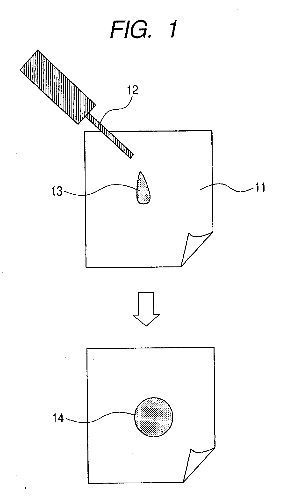
[0098]Example 4 will be described. In Example 4, an aqueous solution of DNA is dropped as a droplet onto a membrane filter. For example, the concentration of 5.4 kb of a vector pcDNA3 aqueous solution is 10 μg / μl and the amount of the aqueous DNA solution is 5 μl. A membrane filter having a pore diameter of about 0.45 μm and a thickness of about 127 μm, the main component of which is hydrophilic nylon, (for example, a membrane filter manufacture by Nihon Pall Ltd., product No. 66607) is used as the membrane filter of this example. The aqueous solution of DNA may be dropped as a plurality of droplets in the same place of the membrane filter to raise the concentration of the solution.

[0099]Then, the membrane filter having the aqueous DNA solution dropped thereon is dried at room temperature. The dried membrane filter is subjected to terahertz wave spectrometry by the method described in Example 1 and a transmittance spectrum is measured. By checking the measurement results against a D...


PUM

PropertyMeasurementUnit
frequencyaaaaaaaaaa
electromagnetic wave amplitude transmittanceaaaaaaaaaa
amplitude transmittanceaaaaaaaaaa

Abstract

Provided are an analysis method and an analysis apparatus that can perform analysis of a substance and information obtainment with relatively high accuracy and reproducibility without previously allowing a carrier to carry a reagent for a color reaction. In the analysis method and the analysis apparatus, the information on an analyte is obtained by using an electromagnetic wave of a frequency including a frequency band which is at least a part of a frequency range of 30 GHz or more and 30 THz or less. A non-fibrous, isotropic porous material is allowed to hold the analyte, the analyte held by the porous material is irradiated with the electromagnetic wave, a change in the propagation state of the electromagnetic wave due to transmission through or reflection by the porous material is detected and information on the analyte is obtained based on the result of the detection.

Description

BACKGROUND OF THE INVENTION[0001]1. Field of the Invention[0002]The present invention relates to a technique directed to an analysis method that involves using a porous material and an electromagnetic wave and performing analysis (detection, identification and the like) of an analyte held by the porous material by irradiating the analyte with the electromagnetic wave. More particularly, the present invention relates to an analysis method and an analysis apparatus for performing analysis of or information obtainment on an objective material by using an electromagnetic wave of a frequency including a frequency band which is at least a part of a frequency range of 30 GHz to 30 THz (hereinafter, referred to as “terahertz wave”).[0003]2. Description of the Related Art[0004]There have hitherto been used methods that involve dropping droplet(s) of an analyte on a carrier such as of a porous material (filter paper, membrane filter, sponge-shaped object), and optically detecting a color reac...

Claims


Application Information

Patent Timeline
Patent Type & Authority Applications(United States)
IPC IPC(8): G01N22/00G01N21/552G01N21/01G01N21/3577G01N21/3586
CPCG01N21/3577G01N21/3581
Inventor KASAI, SHINTAROOUCHI, TOSHIHIKOYONEYAMA, HARUKOYAMASHITA, MASATSUGU
Owner CANON KK
Why Eureka
Try Eureka