
Shock Wave Treatment Device

a treatment device and shock wave technology, applied in the field of shock wave treatment devices, can solve the problems of complex delivery of shock wave to internal organs, difficulty in treating such organs as the heart, cavitation effects, etc., and achieve the effects of dissipating any transmitted acoustic energy, low cost, and effective design

Inactive Publication Date: 2007-10-11
TISSUE REGENERATION TECH
View PDF35 Cites 118 Cited by
  • Summary
  • Abstract
  • Description
  • Claims
  • Application Information

AI Technical Summary

Benefits of technology

[0017]The pulse or wave propagation being emitted from the head on a sideways direction relative to the device enables the surgeon to rotate the head about a longitudinal axis of the device or tilt the head relative to the length of the device providing an infinite number of angular choices for emitting the wave pattern. The device may employ acoustic shock waves from electromagnetic or piezo electric, ballistic or electro hydraulic sources or generators.
[0018]In a preferred embodiment the applicator device is intended for a single surgical procedure and after being used should be discarded. The entire device is accordingly relatively low cost in its manufacture and has a basic but very effective design. The head portion or end includes two electrodes or two tips in one assembly of an electrode to create a shock wave generating spark, and the head portion further includes a reflector for redirecting and shaping the wave pattern. The head is preferably round or oval of a small geometric size sufficient to be positioned under or around the soft tissue of an organ to permit access around the periphery of the organ being treated. Alternatively the reflector and head of the applicator can be an oval of more ellipsoidal shape with the major axis lying along the longitudinal axis of the device. In such a case the minor diameter transverse to the longitudinal axis can be made as small as 4 or 3 cm or preferably 2 cm or less. The device being sealed in a skin membrane has an integral shielding means which would insure the only emitted shockwave energy was directed outward from the reflector cover and the covering through skin membrane overlying these components of the shock wave head. The skin membrane preferably would be a resilient cushion covering thick enough along at least the back and preferably the sides of the applicator head to dissipate any transmitted acoustic energy. In these regions the outer skin preferably is a second material having an outer skin with an inner foam or porosity of entrapped air underlying the skin as is common in some foam filled urethane materials. This is particularly useful to prevent damage to the thin lung membrane during an open heart procedure. Additional shielding means can be made a part of a separate sterile sleeve or even a separate sterile layer positioned between the treated heart and the underlying lung.
[0019]The applicator device may be used by placing it inside a disposable sterile sleeve or cover. In such a case the applicator can be simply cleaned with a disinfecting agent prior to use as it is not directly exposed to the tissue which is greatly improved because the skin membrane is relatively smooth with no crevices. Alternatively the applicator without a separate sleeve or cover can be used wherein the applicator is sterilized prior to use. Preferably each disposable applicator is sealed in a sterile package and gas or radiation sterilized, or steam prior to being used. Ethlyene Oxide gas or any other suitable gas or gamma radiation being typical sterilization sources. In either use the device with the sleeve or cover or the applicator without a cover should be coupled acoustically to the treated tissue or organ by a sterile coupling fluid or viscous gel like ultrasound gels or even NaCl solution to avoid transmission loss.
[0023]The method may further include the steps of activating the applicator device to transmit the shock wave pulses in response to a repetitive body or organ function. In particular the method may include triggering the shock wave pulse during the R phase of the QRS and T curve, alternatively the use of the critical T phase could be used although this is not preferred, or the contraction of a heart wherein the R phase is that portion of the heartbeat depicted by and including the peak amplitude on an ECG monitored display. This controlled pulse triggering avoids irregular heartbeat patterns from being stimulated by the transmission of the shockwave pulses.Definitions

Problems solved by technology

It was believed that the skeletal system of hard bone mass greatly dampened the wave pattern making it difficult to treat such organs as the heart.
In fact, all lasers which have been successfully used for TMR are pulsed systems, and are known to create shock waves in tissue, and resulting cavitation effects.”
The problem of delivery of a shock wave to an internal organ is more complex than simply avoiding bone tissue.
Shock waves inadvertently transmitted to this area can cause bleeding and other damage.
Another problem for the use of shock waves is internal organs are three dimensional masses that in the case of the heart need the waves to be directed from two sides front and back, more preferably from at least three directions.
Another problem associated with such devices is the need to maintain a sterile surgical site in an area surrounded by body fluids and to also avoid electrical shorts and extraneous electrical current flows from the spark generating shock wave applicator device.

Method used


Image

  • Shock Wave Treatment Device
  • Shock Wave Treatment Device
  • Shock Wave Treatment Device

Examples


Embodiment Construction

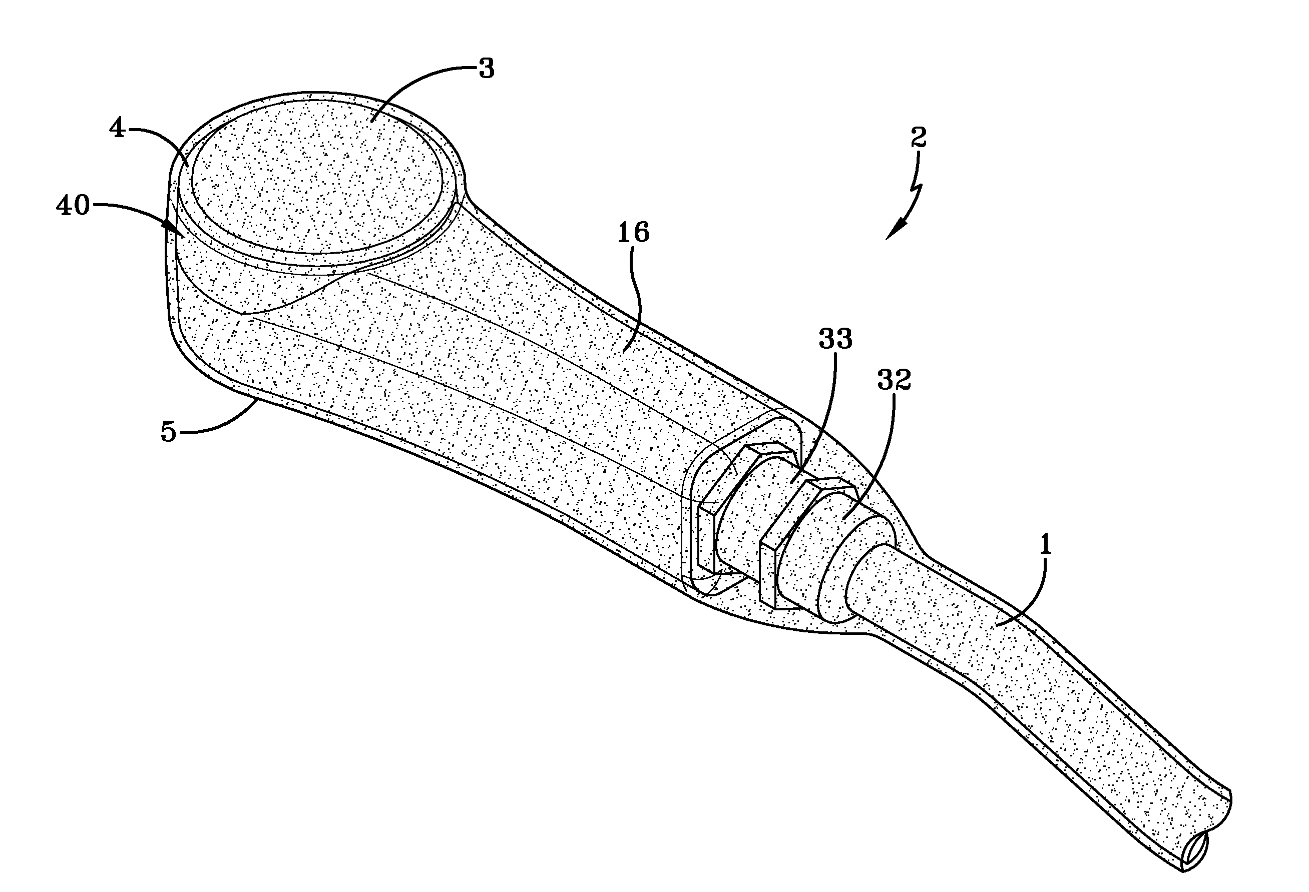
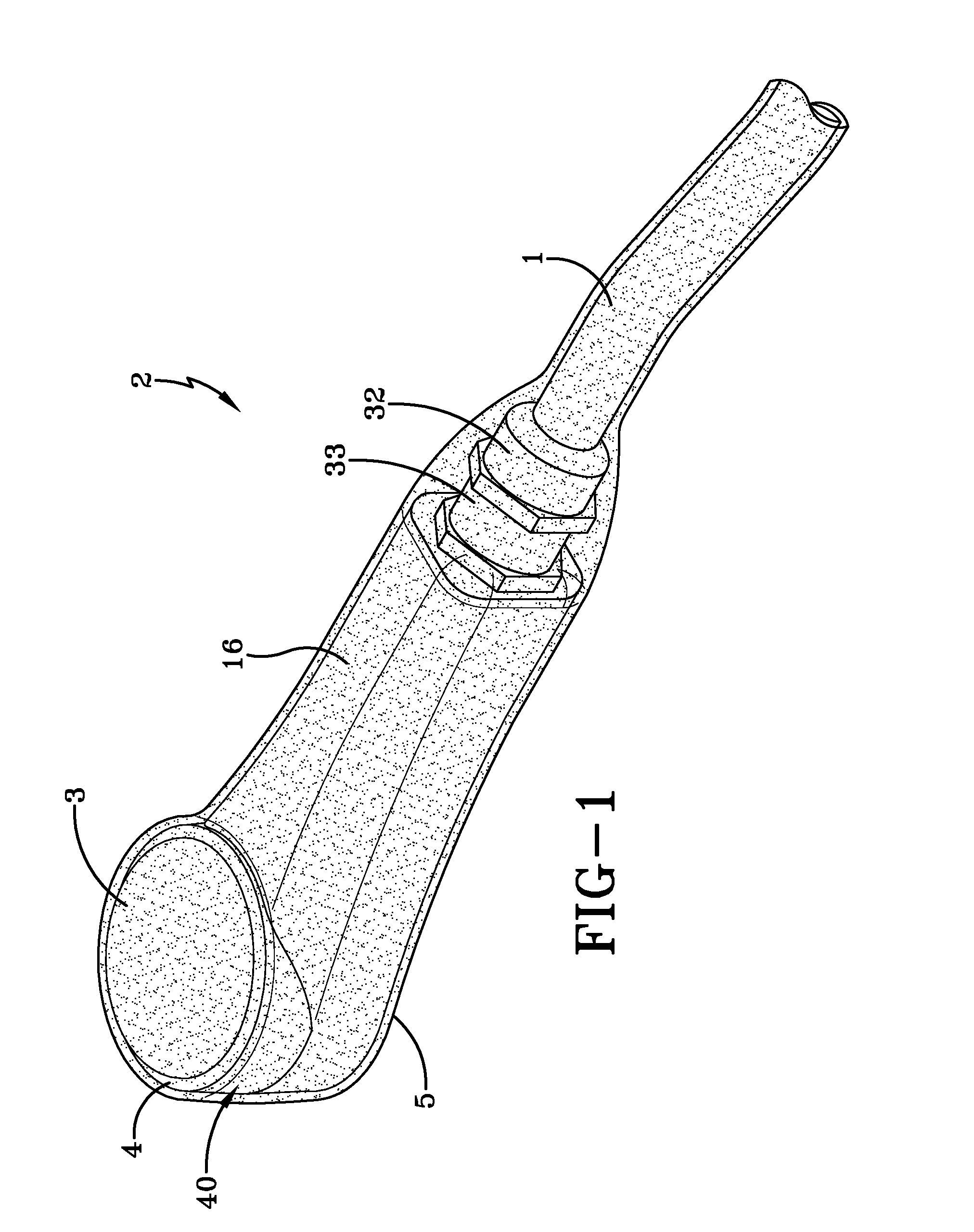
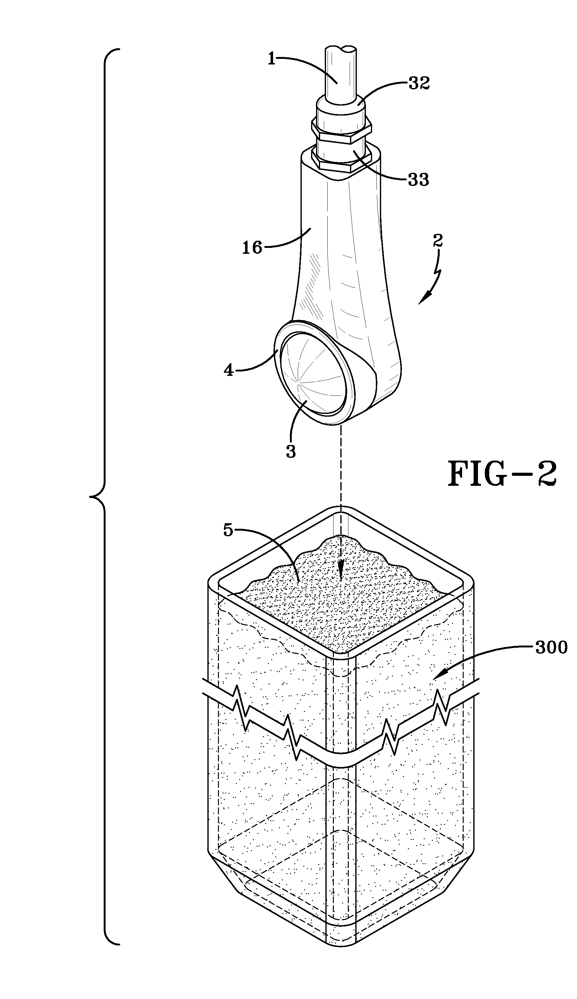
[0057]With reference to FIG. 1 a small portable hand-held shock wave applicator device 2 is illustrated. The shock wave applicator 2 has a cable 1 extending from an end of an applicator housing 16. The cable 1 is connected to a shock wave generator (schematically illustrated in FIG. 12) and as illustrated in FIG. 1 fastened to the applicator housing 16 via a pair of threaded connectors 32, 33.

[0058]At the opposite end of the applicator 2 is an applicator head portion 40 as shown the applicator head portion 40 has a rounded contour with a diameter of approximately 5 cm, preferably smaller which enables the device to be easily positioned around or under the organ to be treated. It is in this portion 40 that the shock wave patterns are produced, reflected and emitted to the organ or tissue 100 being treated. The head portion 40 includes a reflector cover 3 which is sealed and retained by the annular fixation ring 4 which secures and holds the reflector cover 3. The reflector cover 3 is...


PUM


Abstract

The system for treating an internal organ has a generator source for producing a shock wave connected to a handheld or small shock wave applicator device 2, wherein the external housing 16 of the device 2 is hermetically sealed in a non-electrically conductive insulating skin membrane 5 being of a polymer material, preferably a silicone rubber or polyurethane rubber. Preferably the entire device 2 including the connectors 32, 33 and at least a 20 cm portion of attached cable 1 is sealed using a dip coating process or alternatively can use an insert molding process wherein the device 2 is placed in a mold 400 and the skin membrane 5 is injection molded around the entire housing 16 and the cable 1 has an outer skin 5 that abuttingly seals at a connection 32, 33 to the housing 16. The device 2 may further include an internal vacuum conduit connected to a vacuum system to detect leakages and in use may be used with a sterile sleeve cover with a similar vacuum system for leakage detection.

Description

RELATED APPLICATIONS[0001]This application is a continuation in part and claims priority to U.S. Provisional Application No. 60 / 763,018 filed on Jan. 27, 2006 entitled “Shock Wave Treatment and Method of Use” and also claims priority to U.S. Ser. No. 11 / 422,388 filed on Jun. 6, 2006 entitled “Shock Wave Treatment Device and Method of Use”.FIELD OF THE INVENTION[0002]The present invention relates to a method and a device for generating shock waves generally, more specifically to an improved method and device for treating internal organs or tissue.BACKGROUND OF THE INVENTION[0003]The use of shock waves to treat various conditions affecting the bone or soft tissues of a mammal, usually a human is known.[0004]Shock waves produce a high energy pulse that when focused can pulverize hard calcium deposits such as kidney stones. This technology is commonly and very successfully employed in lithotripsy.[0005]More recently, the use of shock waves has been employed in the art of healing non uni...

Claims


Application Information

Patent Timeline
IPC IPC(8): A61H1/00A61H1/02
CPCA61B17/22004A61H23/008A61B2019/083A61B17/2251A61B46/17
Inventor SCHULTHEISS, REINERKNAUSS, JOHANNESSIMNACHER, ERWIN IGNAZ
Owner TISSUE REGENERATION TECH
Learn More