
Chemical reactor with pressure swing adsorption

a technology of pressure swing and reaction reaction, which is applied in the direction of physical/chemical process catalysts, furnaces, separation processes, etc., can solve the problems of incompatibility of prior art separation process and reaction operating temperature, inability to meet the operating temperature of reaction itself, and inability to convert single-pass feed reactants, etc., to achieve the effect of reducing the flow and pressure pulsations seen by the compression machinery

Inactive Publication Date: 2007-11-01
AIR PROD & CHEM INC
View PDF44 Cites 70 Cited by
  • Summary
  • Abstract
  • Description
  • Claims
  • Application Information

AI Technical Summary

Benefits of technology

[0010] The present invention conducts a chemical reaction in cooperation with a rotary module for pressure swing adsorption separation of the reaction product(s) from the reactant(s), with high energy efficiency and with compact machinery of low capital cost.
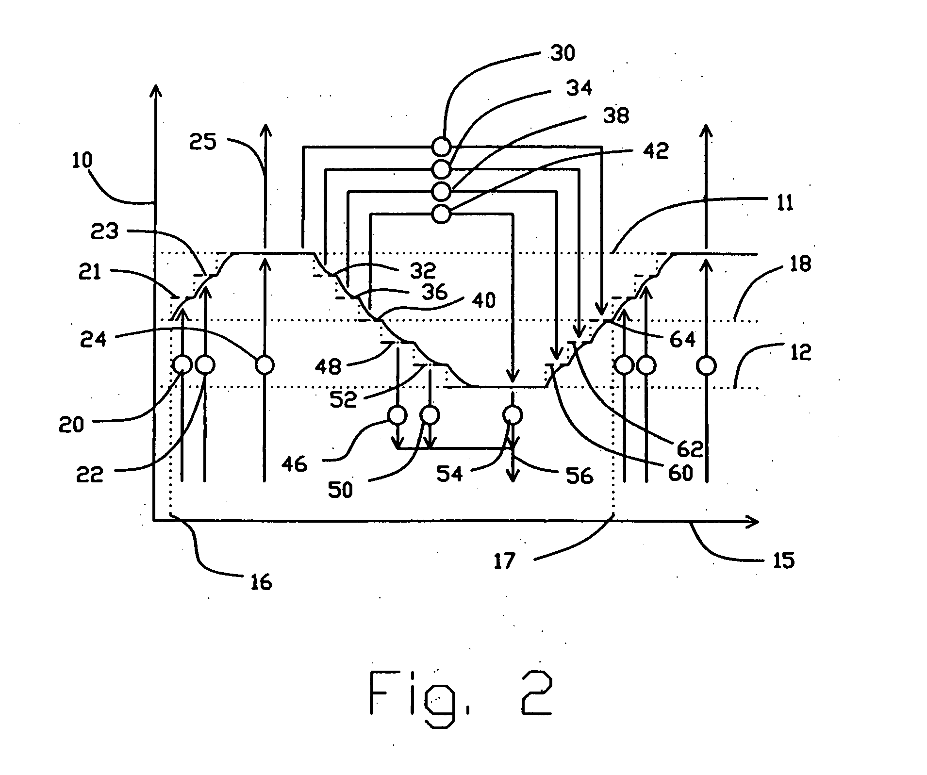
[0014] In the present invention, the feed compressor will typically supply feed gas, in several stages at discrete intermediate pressures for feed pressurization of the adsorbers as well as the higher pressure for light product production, to the first valve means. The exhauster will typically receive second product gas, in several stages at discrete intermediate pressures for countercurrent blowdown of the adsorbers as well as the lower pressure, from the first valve means. The light reflux expander may also perform pressure let-down on several separate light reflux stages, sequentially drawn from the second valve means at a set of discrete intermediate pressure levels, and after expansion returned to the second valve means at a lower set of discrete intermediate pressure levels. Heat exchangers may be provided to heat gas streams about to be expanded, for thermally boosted energy recovery.
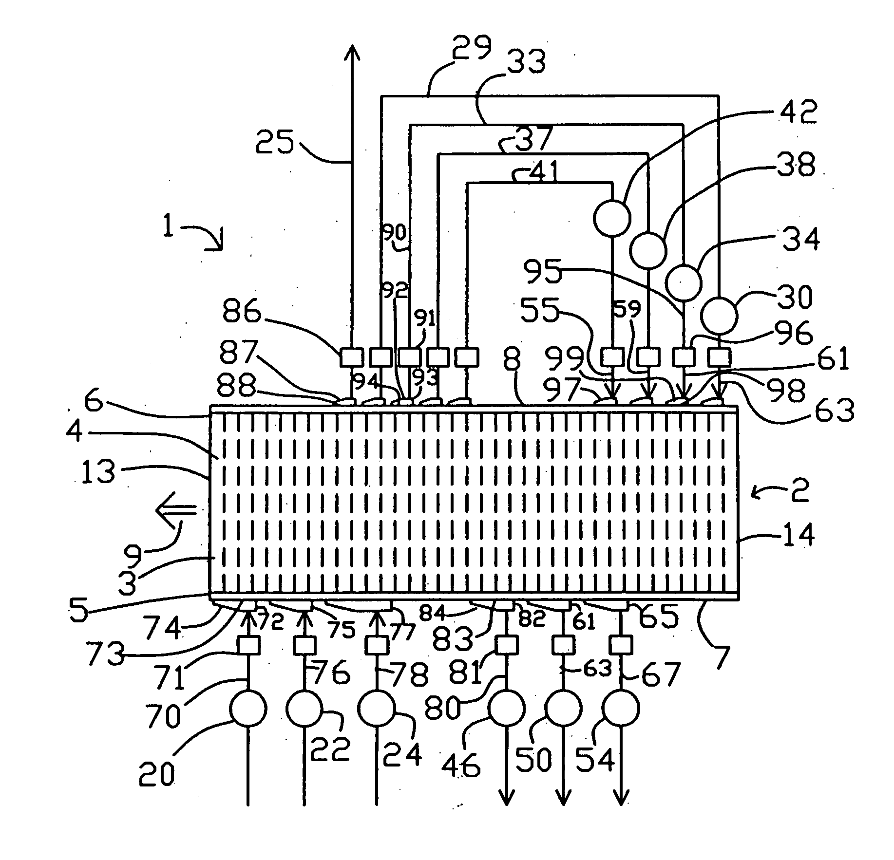
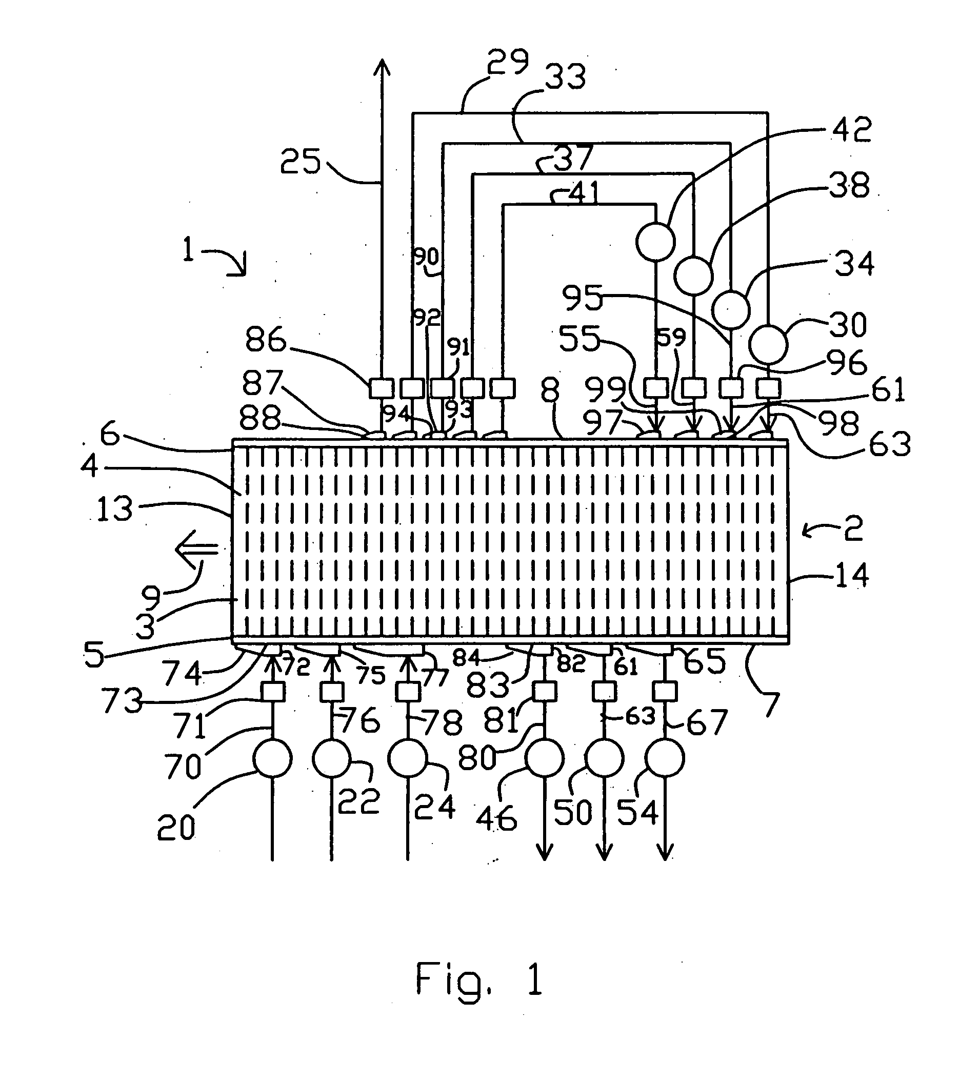
[0016] A preferred way to provide a large number of adsorbers in a mechanically simple PSA module is to instal those adsorbers as angularly spaced elements in a rotor, whose opposed faces engaging across sealing faces with a ported stator sealing faces will provide the first and second valve means. By providing a sufficient number of ports with suitable angular spacing to accommodate each of the desired pressure levels (higher, lower and intermediate) in each of the first and second valve faces, a desired PSA cycle can be achieved.
[0017] If a smaller number of adsorbers is used in each PSA module, surge absorber chambers will be needed to isolate each stage of the compression machinery from excessive pulsations of flow and pressure. With sufficiently large surge absorber chambers, flow and pressure pulsations seen by the compression machinery are again minimized.

Problems solved by technology

Fundamental problems in the chemical process industry include management of reaction equilibrium and kinetics to achieve high conversion with desired selectivity under moderate reaction conditions, and management of the heat of reaction to control reaction temperature and to achieve high energy efficiency.
Typically, single pass conversion of the feed reactant(s) is incomplete because of equilibrium limitations.
In most cases, these prior art separation processes are incompatible with the operating temperature of the reaction itself.
Most conventional separation processes operate at ambient or sub-ambient temperature, while the reaction operates at elevated temperature so that costly heat exchangers are required for the recycle loop.
The high cost of heat exchangers, recycle compressors, and other auxiliary equipment then incentivizes operation at relatively severe pressure or temperature reaction conditions to minimize the need for recycle.
This conventional pressure swing adsorption process makes inefficient use of applied energy, because of irreversible expansion over the valves over large pressure differences while switching the adsorbent beds between higher and lower pressures.

Method used


Image

  • Chemical reactor with pressure swing adsorption
  • Chemical reactor with pressure swing adsorption
  • Chemical reactor with pressure swing adsorption

Examples


embodiment 200

[0052] Section 200A shows the first valve face of embodiment 200 of FIG. 4, at section 202-203, with fluid connections to feed and to countercurrent blowdown. Arrow 270 indicates the direction of rotation by adsorber rotor 2. The open area of valve face 107 ported to the feed and exhaust compartments is indicated by clear angular segments 77, 82, 61, 65, 72, 75, and 77 corresponding to those functional compartments, between circumferential seals 215 and 216. The substantially closed area of valve face 107 between functional compartments is indicated by cross-hatched sectors 275 and 276 which are clearance slippers 130. Typical closed sector 275 provides a transition for an adsorber, between being open between two adjacent compartments. Gradual opening is provided by a tapering clearance channel between the slipper and the sealing face, so as to achieve gentle pressure equalization of an adsorber being opened to a new compartment. Much wider closed sectors (e.g. 276) are provided to ...

embodiment 500

[0072] Embodiment 500 is an apparatus for conducting an endothermic reaction, with the chemical reaction performed in reactors external to the rotary module. The PSA cycle pattern is shown in the lower part of FIG. 8. An example application is ammonia dissociation to generate reducing gas as hydrogen.

[0073] Reactors 501, 502 and 503 are interposed in conduits 78, 76 and 70 supplying gas to the first valve face 7. If desired, only one reactor (e.g. 501) could be provided. A feed gas containing a relatively more readily adsorbed reactant is supplied to a stage of heavy reflux compressor 340 by infeed conduit 504, which may as needed include a vaporizer 505 to ensure that the reactant(s) are in the vapour phase. Gas enriched in a more readily adsorbed reactant component is withdrawn as heavy reflux gas by conduits 80, 63 and 67 from countercurrent blowdown and exhaust compartments in the first valve face, and is thence delivered to inlet ports of heavy reflux compressor stages. The hea...

embodiment 600

[0075] Embodiment 600 is an apparatus for conducting an endothermic reaction, with the chemical reaction performed within the rotary module which itself is a heat exchange reactor. An example application is steam methane reforming to produce hydrogen from natural gas. A steam reforming catalyst (e.g. nickel or a platinum group metal supported on alumina) and a high temperature carbon dioxide sorbent are supported in the adsorbers 3. The carbon dioxide sorbent may be based on potasssium carbonate promoted hydrotalcite as developed by J. R. Hufton, S. G. Mayorga and S. Sircar (“Sorption Enhanced Reaction Process for Hydrogen Production”, AIChEJ 45, 248 (1999)), or another high temperature carbon dioxide sorbent likewise effective in the presence of high steam partial pressure. This sorbent has good working capacity for carbon dioxide in the temperature range of 400° C. to 500° C.

[0076] In the steam methane reforming application of embodiment 600, the working temperature of the adsorbe...


PUM

PropertyMeasurementUnit
rotationaaaaaaaaaa
lengthaaaaaaaaaa
lengthaaaaaaaaaa

Abstract

A chemical reaction is performed with separation of the product(s) and reactant(s) by pressure swing adsorption (PSA), using an apparatus having a plurality of adsorbers cooperating with first and second valve assemblies in a PSA module. The PSA cycle is characterized by multiple intermediate pressure levels between higher and lower pressures of the PSA cycle. Gas flows enter or exit the PSA module at the intermediate pressure levels as well as the higher and lower pressure levels, entering from compressor stage(s) or exiting into exhauster or expander stages, under substantially steady conditions of flow and pressure. The PSA module comprises a rotor containing the adsorbers and rotating within a stator, with ported valve faces between the rotor and stator to control the timing of the flows entering or exiting the adsorbers in the rotor. The reaction may be performed within a portion of the rotor containing a catalyst.

Description

FIELD OF THE INVENTION [0001] The invention relates to chemical reactions conducted in the gas or vapour phase. Reactions may be exothermic or endothermic, and may be conducted over a catalyst or under an appropriate form of external excitation to stimulate the reaction. Some particular applications include ammonia synthesis, methanol synthesis, conversion of natural gas or syngas to liquid fuels, hydrogenation and dehydrogenation reactions, and controlled oxidation reactions. BACKGROUND OF THE INVENTION [0002] Fundamental problems in the chemical process industry include management of reaction equilibrium and kinetics to achieve high conversion with desired selectivity under moderate reaction conditions, and management of the heat of reaction to control reaction temperature and to achieve high energy efficiency. [0003] Typically, single pass conversion of the feed reactant(s) is incomplete because of equilibrium limitations. It is then often necessary to provide a separation system...

Claims


Application Information

Patent Timeline
Patent Type & Authority Applications(United States)
IPC IPC(8): B01J8/18B01D53/047B01D53/06B01J19/28C07B61/00C07C1/04C07C2/84C07C9/22C07C11/04C07C29/152C07C31/04
CPCB01D53/047B01D53/06Y02C10/08B01D2259/40005B01D2257/504Y02P20/582Y02C20/40
Inventor KEEFER, BOWIE G.CONNOR, DENIS J.
Owner AIR PROD & CHEM INC
Learn More