Thermal oxidation protective surface for steel pistons

Active Publication Date: 2007-11-15
FEDERAL MOGUL WORLD WIDE LLC
View PDF46 Cites 34 Cited by
  • Summary
  • Abstract
  • Description
  • Claims
  • Application Information

AI Technical Summary

Benefits of technology

[0011] The subject method and piston structure overcome the shortcomings and deficiencies of prior art pistons by intentionally preparing and treating the lip region of the piston crown, comprising the interface between the annular rim and the concave bowl so that it can better withstand the abusive effects of combus

Problems solved by technology

If the air-fuel mixture fails to completely fill the bowl in the piston crown, both air utilization and power output will suffer.
Likewise, if there is an overlap and the mixture extends beyond the space between the individual injection events, the resulting excessive local fuel concentration will lead to air deficiencies and increased soot formation, again, decreasing the anti-polluting emission characteristics of the engine.
In addition to these timing issues, another problem contributes to a loss of the anti-polluting emission characteristics designed for the piston.
This change in the shape of the bowl lip causes disturbances in the combustion process and contributes to a loss of the an

Method used


Image

  • Thermal oxidation protective surface for steel pistons
  • Thermal oxidation protective surface for steel pistons
  • Thermal oxidation protective surface for steel pistons

Examples


Embodiment Construction

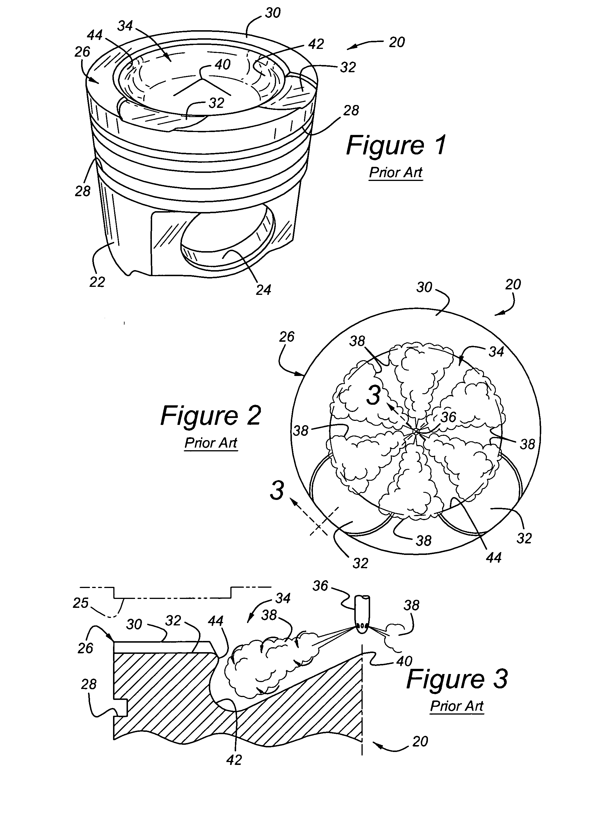
[0025] Referring to the figures, wherein like numerals indicate like or corresponding parts throughout the several views, a steel piston for a fuel-injected diesel engine is generally shown at 20 in FIG. 1. The piston 20 is of the type adapted for use in a fuel-injected diesel engine. The piston 20 comprises a generally cylindrical skirt portion 22, having a pair of opposing pin bores 24 formed transversely therein. The skirt 22 guides and supports the piston 20 as it reciprocates in the cylinder (not shown) of a diesel engine, while the pin bores 24 receive a wrist or gudgeon pin, which attaches to the upper end of a connecting rod (not shown) and, ultimately, to the crank shaft of the engine. A crown, generally indicated at 26, is affixed atop the skirt 22. In the preferred embodiment of this invention, the skirt 22 and crown 26 are integrally formed of a unitary steel material. The composition of material can be selected from any of the known varieties, including but not limited ...


PUM

PropertyMeasurementUnit
Fractionaaaaaaaaaa
Angleaaaaaaaaaa
Angleaaaaaaaaaa

Abstract

A piston (120) and method for making a piston (120) for a fuel-injected diesel engine adapted to withstand the damaging effects of fuel injection plume-induced oxidation in the regions of the piston bowl (134) and rim (130). The surfaces of the piston crown (126) targeted by the fuel injection plume (138) are first coated with a corrosion-resistant and oxidation-resistant composition applied as a slurry or by a thermal spraying technique, such as HVOF or plasma spraying. Thereafter, a high energy industrial laser beam irradiates the as-sprayed coating to increase its density, while simultaneously reforming its microstructure so as to fuse, alloy, and materially bond the coating material with the underlying steel substrate, thereby resulting in a durable protective surface for the steel piston crown (126).

Description

BACKGROUND OF THE INVENTION [0001] 1. Field of the Invention [0002] The subject invention relates to a piston for a diesel engine and method of making such a piston having a crown specially treated to resist thermal oxidation degradation and, more particularly, to such a piston of the steel type used in fuel-injected diesel engine applications. [0003] 2. Related Art [0004] A diesel engine is a reciprocating-piston engine operating on the well-known thermodynamic cycle in which air is compressed, fuel is injected into the compressed charge, the auto-combusting mixture expanded to do work on the piston, and the products exhausted at completion of the cycle. In large steel pistons such as used in diesel truck applications, it is common to utilize a multiple-orifice nozzle to inject fuel during the combustion process. The nozzle with multiple orifices is located as centrally as possible above the piston crown and discharges fuel in a radial spray pattern. A depressed bowl in the piston ...

Claims


Application Information

Patent Timeline
IPC IPC(8): F02B19/00F02F3/00F02F3/26F02B75/08B23P15/10
CPCB23K26/34Y10T29/49249C23C4/005C23C4/18F02B23/0603F02B23/0696F02B75/08F02F3/12F02F3/14F02F3/26F16J1/01Y02T10/125B23K26/3206B23K35/38B23K2201/003C23C4/01B23K26/32C23C24/04B23K2101/003B23K2103/50Y02T10/12C23C24/08B22F7/00C23C4/04
Inventor LINETON, WARRANAZEVEDO, MIGUEL
Owner FEDERAL MOGUL WORLD WIDE LLC
Why Eureka
Try Eureka