
Anti-reflective film and production method thereof, and stamper for producing anti-reflective film and production method thereof

a technology of anti-reflective film and stamper, which is applied in the direction of printing, reproduction, printing, etc., can solve the problems of difficult to produce inexpensive stampers, difficult to control the taper shape, and difficult to form the optimum tapered shape required for the formation of a non-reflective layer, so as to reduce reflection

Active Publication Date: 2007-12-20
KANAGAWA INST OF IND SCI & TECH
View PDF6 Cites 38 Cited by
  • Summary
  • Abstract
  • Description
  • Claims
  • Application Information

AI Technical Summary

Benefits of technology

[0011]Therefore, in order to solve the aforementioned problems of the prior art, an object of the present invention is to provide a method for producing an anti-reflective film which is able to form a desired anti-reflective film on the surface of a polymer molding material by using anodic oxidized porous alumina as a mold, an anti-reflective film formed by the method, a stamper which is able to efficiently form the anti-reflective film, and a method for producing the stamper.
[0014]In addition, the use of the anodic oxidized porous alumina produced by anodic oxidation at about the same formation voltage and pore diameter enlargement treatment, after having carried out anodic oxidation for an extended period of time at a constant voltage followed by temporarily removing an oxide film, makes it possible to use as a mold the anodic oxidized porous alumina having highly orderly arrangement of pores.
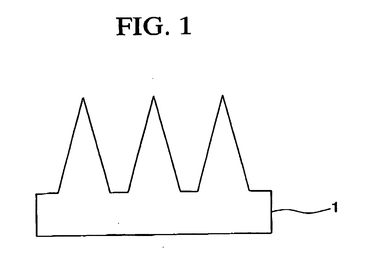
[0017]An anti-reflective film of the present invention is produced according to such a method, and has superior anti-reflection performance due to surface unevenness formed in a desired shape. In particular, this anti-reflective film is able to demonstrate the target level of anti-reflection performance in various applications as a result of being formed on the surface of a light-transmitting polymer molding material.
[0020]According to the present invention, a mold can be formed based on anodic oxidized porous alumina, for which taper shape has been controlled, more easily than methods of the prior art. As a result, the present invention enables an anti-reflective film which reduces reflection in the visible light range, a production method thereof, a stamper for forming an anti-reflection layer, and a method for producing the stamper.

Problems solved by technology

As described above, in methods using lithography, it is difficult to inexpensively produce a stamper which is able to process a large surface area, while also being difficult to control the taper shape.
In addition, even in techniques using anodic oxidized porous alumina, there was the problem of it being difficult to form the optimum tapered shape required for the formation of a non-reflective layer.

Method used


Image

  • Anti-reflective film and production method thereof, and stamper for producing anti-reflective film and production method thereof
  • Anti-reflective film and production method thereof, and stamper for producing anti-reflective film and production method thereof
  • Anti-reflective film and production method thereof, and stamper for producing anti-reflective film and production method thereof

Examples


example 1

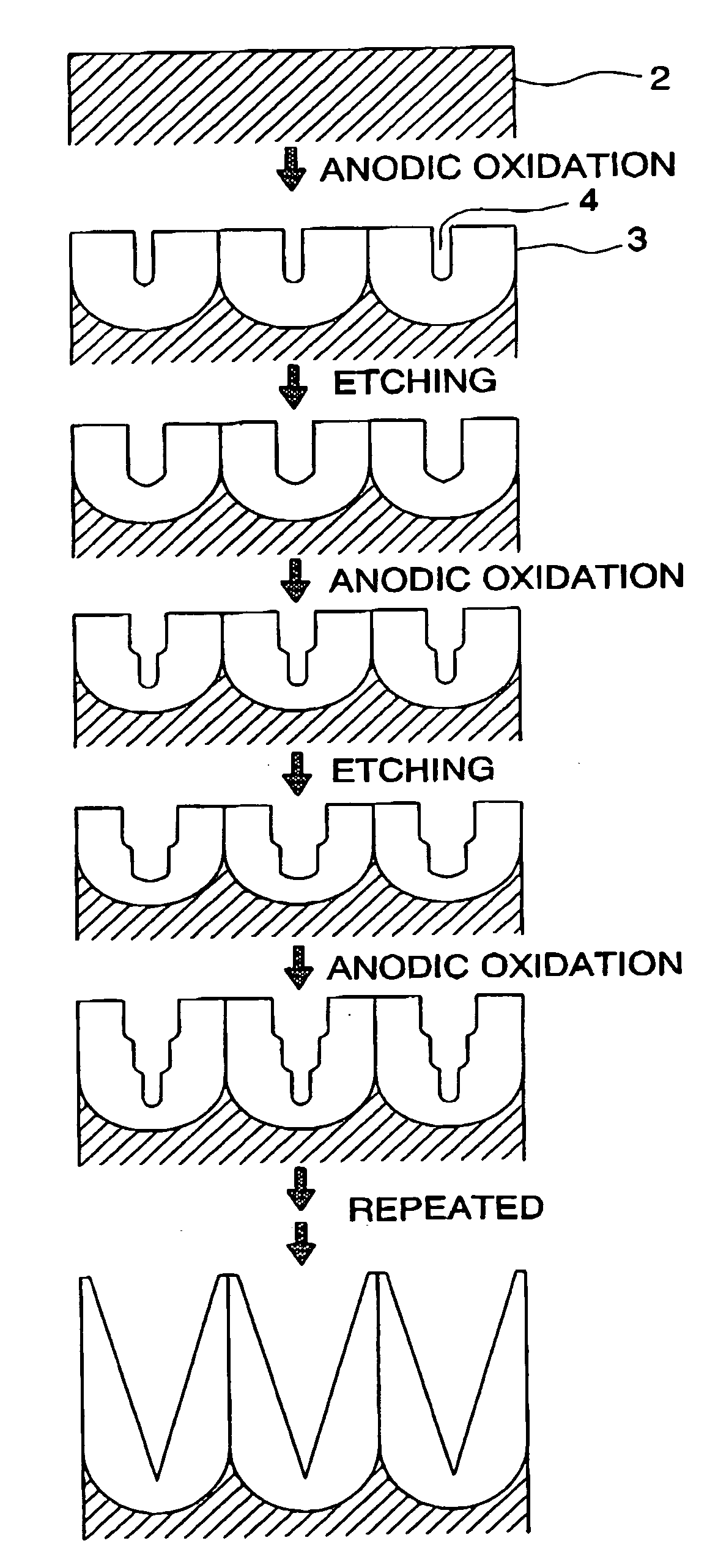
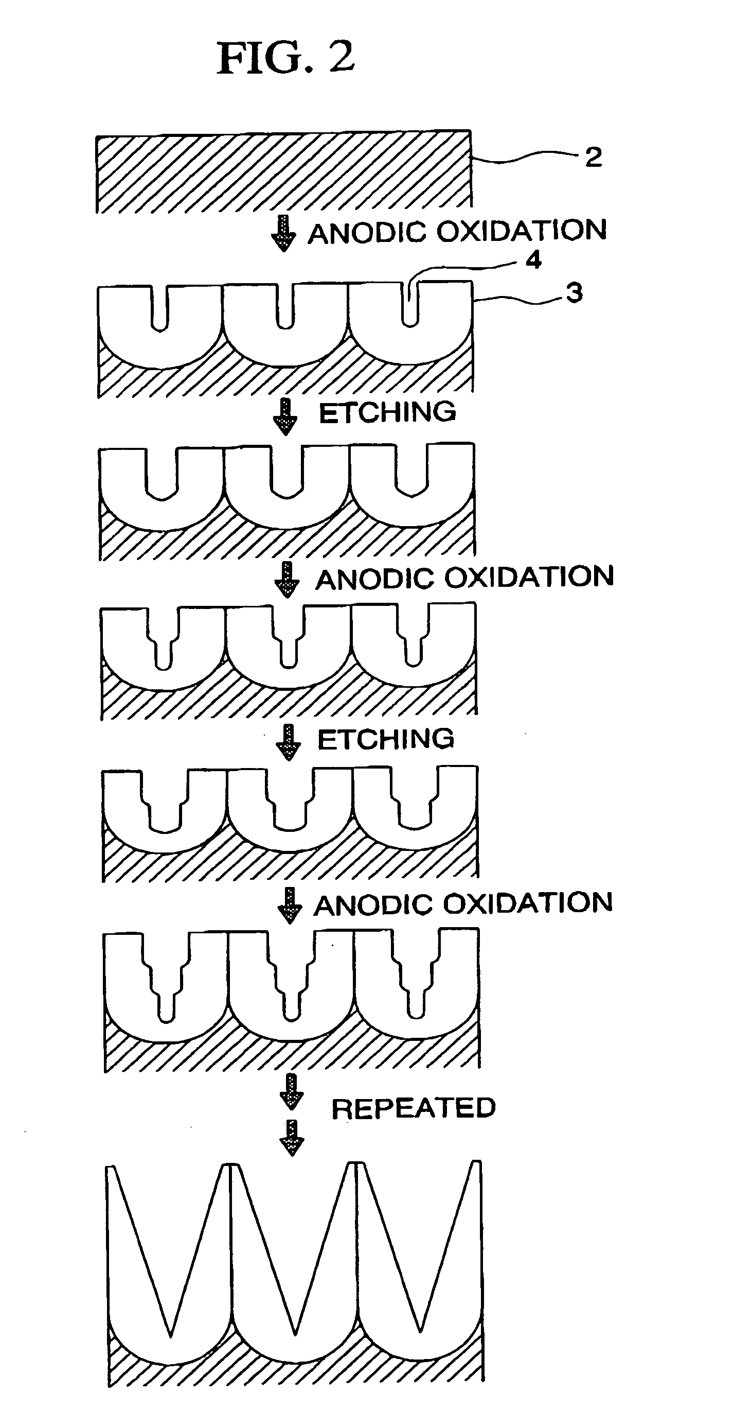
[0044]Anodic oxidation was carried out on an aluminum sheet of 99.990% purity for 50 seconds at a temperature of an electrolyte of 17° C., formation voltage of 40 V, and using 0.3 M oxalic acid for the electrolyte. Subsequently, pore diameter enlargement treatment was carried out by immersing for 5 minutes in 2% by weight phosphoric acid at 30° C. This procedure was repeated five times to obtain anodic oxidized porous alumina having tapered pores having a period of 100 nm, pore diameter opening of 80 nm, bottom of 25 nm, and pore depth of 300 nm.

[0045]After filling the pores with methyl methacrylate monomer containing benzoyl peroxide of 5% by weight as a polymerization initiator, the monomer was polymerized by irradiating with ultraviolet light. Following polymerization, the polymer layer was separated from the mold to obtain polymethyl methacrylate resin having an arrangement of projections on the surface thereof. As a result of measuring the reflectance of the resulting polymer f...

example 2

[0046]Anodic oxidation was carried out on an aluminum sheet similar to that of Example 1 for 6 seconds at a temperature of an electrolyte of 17° C., formation voltage of 25 V and using 0.3 M sulfuric acid for the electrolyte. Subsequently, pore diameter enlargement treatment was carried out by immersing for 3 minutes in 10% by weight phosphoric acid at 30° C. After repeating this procedure five times, anodic oxidation was carried out for an additional 6 seconds to obtain anodic oxidized porous alumina having tapered pores having a period of 63 nm, pore diameter opening of 55 nm, bottom of 20 nm, and pore depth of 170 nm. Subsequently, reflectance was confirmed to have decreased as a result of trusferring the structure to a polymethyl metbacrylate resin in the same manner as Example 1.

example 3

[0047]After carrying out anodic oxidation on an aluminum sheet in the same manner as Example 1 for 2 hours at a temperature of an electrolyte of 17° C., formation voltage of 40 V and using 0.3 M oxalic acid for the electrolyte, the porous alumina layer was selectively dissolved and removed by a mixed solution of phosphoric acid and chromic acid. Subsequently, anodic oxidation and pore diameter enlargement treatment were repeated under the same conditions as Example 1 to obtain anodic oxidized porous alumina having tapered pores in which the pores were arranged with high regularity. Subsequently, reflectance was confirmed to have decreased as a result of tansferring the structure to a polymethyl methacrylate resin using the same procedure as Example 1.


PUM

PropertyMeasurementUnit
pore depthaaaaaaaaaa
formation voltageaaaaaaaaaa

Abstract

In this method for producing an anti-reflective film, pores are formed on a surface of a polymer molding material to continuously change a refractive index and then reduce reflectance, in which anodic oxidized porous alumina, in which pores having a tapered shape and whose pore diameter continuously changes, are formed by repeating anodic oxidation at about the same formation voltage and pore diameter enlargement treatment, is used as a mold, or a stamper, which is produced by using the anodic oxidized porous aluminum as a mold, is used as a mold.

Description

BACKGROUND OF THE INVENTION[0001]1. Field of the Invention[0002]The present invention relates to an anti-reflective layer (anti-reflective film) formed on the surface of a polymer molding material which reduces reflection in the visible light range and a production method thereof, and a stamper for forming the anti-reflective film and a production method thereof[0003]2. Description of Related Art[0004]Polymer molding materials are widely used in various information equipment display devices. It is necessary to form an anti-reflective layer to inhibit reflected light to ensure satisfactory visibility. Multilayer films composed of dielectrics having different refractive indices are normally used as anti-reflective layers. Since vacuum deposition or sputtering is used to form the dielectric layer, there was the problem of requiring expensive devices and considerable production time to form the reflective layer.[0005]On the other hand, a method for reducing reflectance is known in which...

Claims


Application Information

Patent Timeline
Patent Type & Authority Applications(United States)
IPC IPC(8): C25D11/02B41C3/08C25D11/00A01J21/00
CPCC25D1/10C25D11/12Y10T428/24479G02B1/118C25D11/18
Inventor MASUDA, HIDEKIYASUI, KENJIKAWAMOTO, YASUSHI
Owner KANAGAWA INST OF IND SCI & TECH
Learn More