[0009]The present disclosure provides a device that can generate a significant amount of power (beyond the need of a standard pacemaker) and be delivered percutaneously. It was found that a device that increases the natural velocity or acceleration of the
heart muscles (to increase the
induced voltage) and at the same time extends the duration of the current, by using a low loss mechanical
resonator, can provide sufficient power in such a small volume.
[0010]One simple way to increase the speed of movement created by the
heart muscles is to power the device from the blood pressure and not directly from the
muscle movement. It is well known that the blood pressure inside the heart, and in particular inside the left
ventricle, rises and falls very fast. A bellows responding to this rapid change in blood pressure will move significantly faster than the wall of the
ventricle. The reason is that the wall area is much larger than the area of the bellows, so a small movement of the wall creates a large change in volume, causing the bellows to move a significant amount. Prior attempts to use this principle, such as US RE30,366, fails to take into account the very low pressure differentials inside the heart in comparison to
atmospheric pressure, thus the energy extracted will be only a small fraction of the estimated power. For example, RE30,366 estimates that the 20 mmHg pressure pulse of the right
ventricle will move the
transducer 1 mm, generating 130 micro
joule of energy (page 8 line 32) while the actual number is only a small fraction of this number. The reason is that any movement of the bellows will increase the air pressure inside the device. In a 1 cm long
enclosure, even if the
enclosure was completely empty, the movement will only be: 10 mm×20 mmHg / 760 mmHg=0.26 mm. When
enclosure is filled with the necessary pacemaker
electronics, movement is further reduced. In order to achieve high efficiency the
transducer has to avoid the increase in internal air (or gas) pressure when its volume is changing. The present embodiments allow movements of several millimeters from very low pressure changes, with corresponding increases in output power.
[0013]In one aspect, a self-powered pacemaker of such small size that it can be implanted at the point of the desired stimulation, thus requiring no leads. The small size also allows
percutaneous implantation and replacement, as the device is small enough to fit through the catheters currently used in
percutaneous cardiac surgery. If desired, the device can be used with conventional pacing leads. The device can also be used simply as an electrical energy generator inside the body. It can be placed in the heart or in any major
artery to supply
electricity for devices other than pacemakers, for example de-fibrillators,
drug delivery devices, brain stimulators etc. A device having a volume of about two cubic centimeters can supply over approximately 33 microwatts continuously. The theoretical possible
power output from a one cubic
centimeter device placed in the left ventricle of the heart and powered by the blood pressure variation is about 10 mW, thus less than 1% efficiency is required to power a pacemaker. In another aspect, a device may be tolerant to large changes in
ambient air pressure without electrical output being affected. In yet another aspect, a very reliable device is not subject to internal wear, by avoiding any
internal friction and basing all motions on flexure instead of bearings.
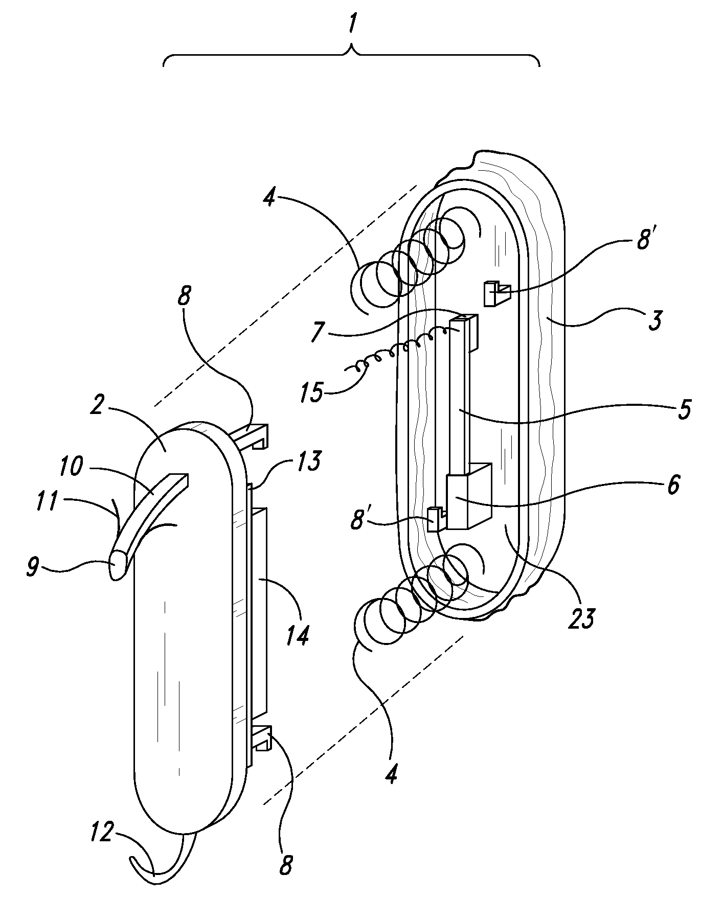
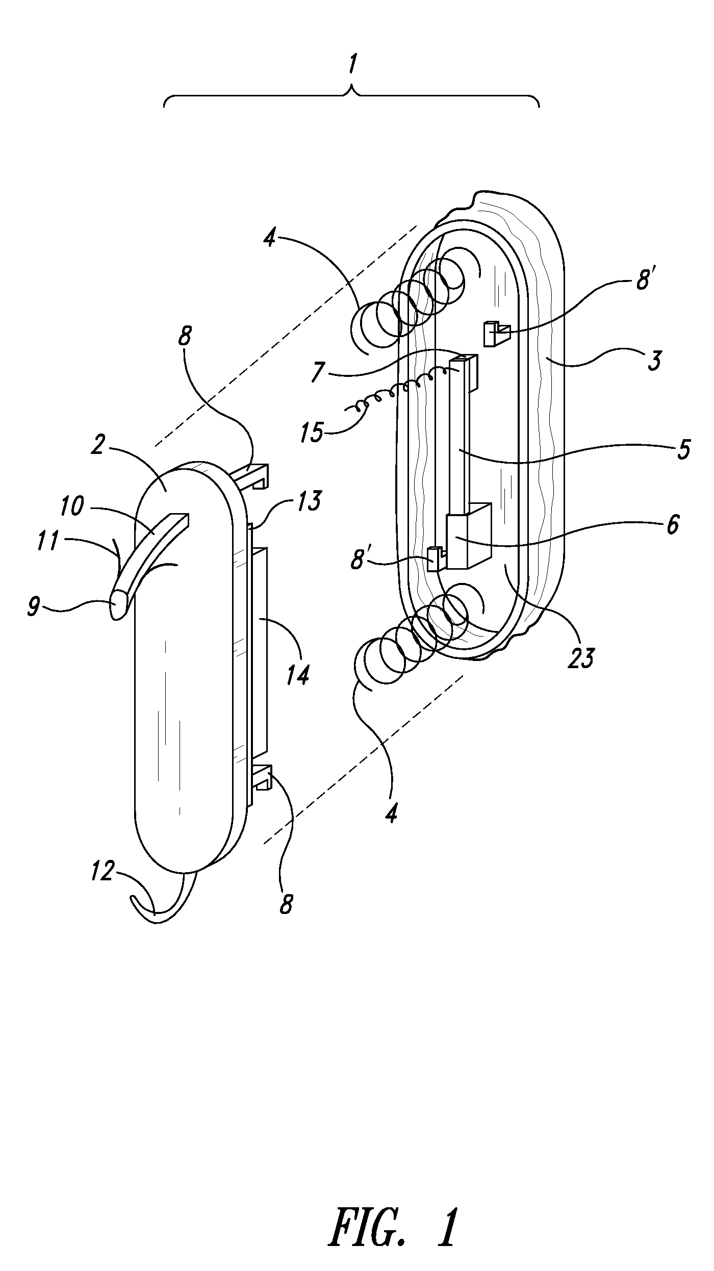
[0014]In at least one embodiment, a device uses the variations of blood pressure inside the heart, or a major
artery, to create a periodic change in the
magnetic flux inside a coil by resonating a
mass-
spring system. Typically the pressure variations compress a bellows carrying a
magnet resonating inside a coil. The inside of the bellows can be evacuated to a partial or full vacuum, and a spring restores the bellows to the desired
equilibrium point, acting against the blood and
atmospheric pressure. The electrical pulses may be stored in a
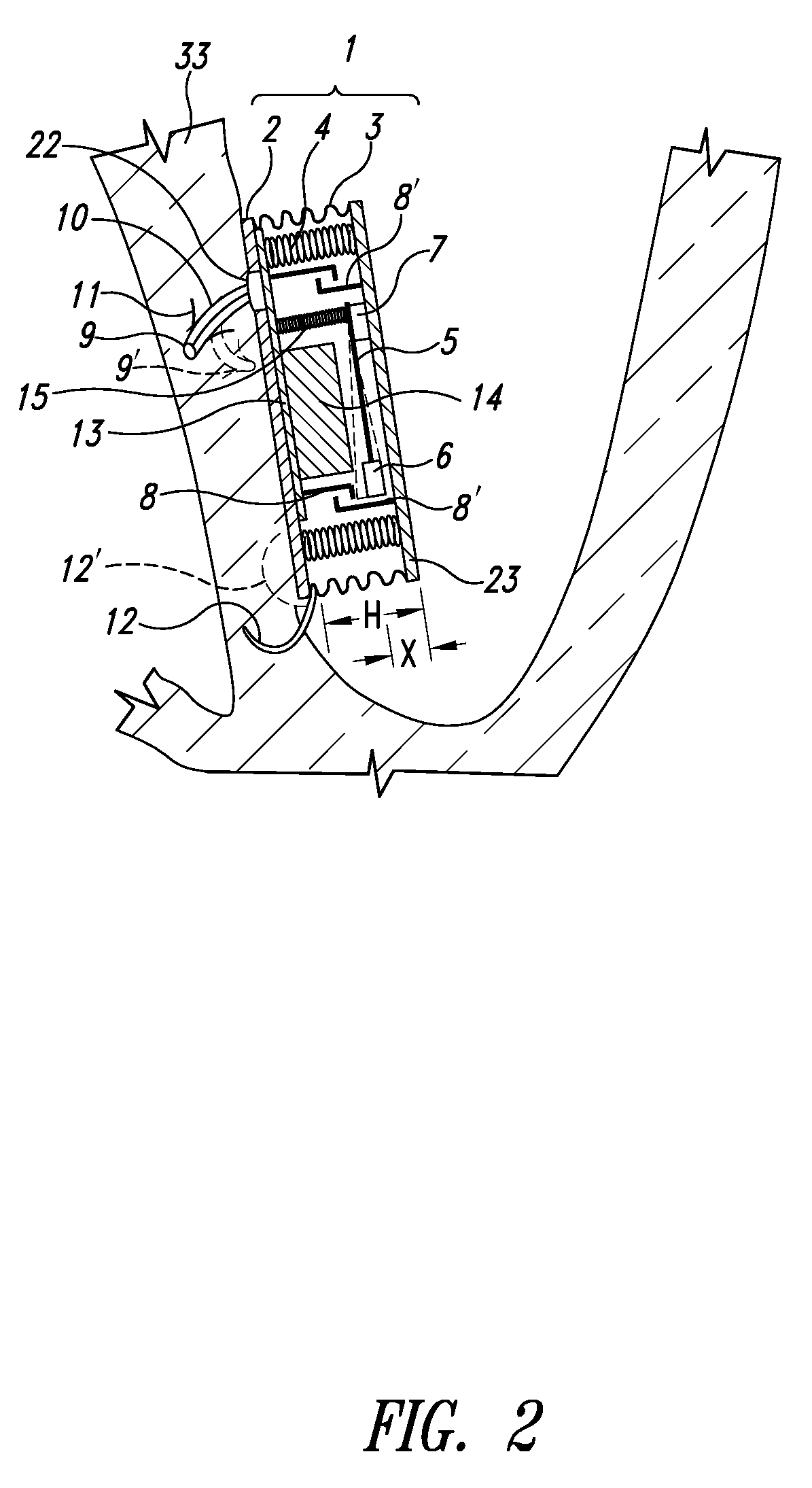
capacitor, and used to power a pacemaker or other devices. Since most of the volume of a pacemaker is the battery, eliminating the battery allows dramatic
miniaturization of the pacemaker, to the point it can be implanted at the point of desired stimulation. There is no other mechanical
coupling to the
heart motion except via the changes in blood pressure. This minimizes the interference with the operation of the heart. The
compressibility of the device volume with increased pressure is actually an
advantage, as it reduces the blood pressure peaks. The device allows for the
ambient air pressure to change by allowing the bellows to change length without affecting electrical output.

