Printing form precursor and process for preparing a stamp from the precursor

a technology of precursor and printing form, which is applied in the field of printing form precursor, can solve the problems of pdms severely limiting its capabilities, inability to easily control the surface energy of pdms, and breakage of the polymer chain

Inactive Publication Date: 2008-01-03
EI DU PONT DE NEMOURS & CO
View PDF10 Cites 122 Cited by
  • Summary
  • Abstract
  • Description
  • Claims
  • Application Information

AI Technical Summary

Problems solved by technology

However, several properties inherent to PDMS severely limit its capabilities.
Additionally, acidic or basic aqueous solution react with PDMS that can cause breakage of the polymer chain.
Secondly, the surface energy of PDMS can not be easily controlled and can cause difficulties in printing procedures that require high fidelity.
These fluorine treated silicones still swell however when exposed to organic solvents.
Third, the most commonly used commercially available form of the material used in PDMS molds, SYLGARD silicone elastomer base from Dow Chemicals, has a modulus that is too low for many applications.
The low modulus of these commonly used PDMS materials results in sagging and bending of features and as such is not well suited for processes that require precise pattern placement and alignment.
These materials are superior to PDMS in modulus and swelling resistance, but lack flexibility.
Such lack of flexibility inhibits conformal contact with the substrate and causes defects in the mold and / or replicate during separation.
Another drawback of rigid materials is the necessity to use a costly and difficult to fabricate hard mold, which is typically made by using conventional photolithography or electron beam (e-beam) lithography.
Freestanding stamps made of PFPE can have a problem with dimensional instability; that is, elastomeric layer can deform or warp during formation and during use.
Further, it is difficult to form relatively large dimension (on the order of 12 by 12 in) freestanding stamps having uniform thickness of the elastomeric material.
For U.S. Pat. No. 6,656,308 B2 the flat and rigid planar member prevents undulations of the flexible backplane arising from shrinkage of the thermal curing elastomeric layer, since the flexible backplane alone is not sufficient to prevent undulation problems.
This process of fabricating the stamp is rather cumbersome and time-consuming as it presents additional steps of laminating the flexible backplane to the rigid planar member, and after thermal curing the elastomer, delaminating the flexible backplane from the rigid planar member.

Method used


Image

  • Printing form precursor and process for preparing a stamp from the precursor
  • Printing form precursor and process for preparing a stamp from the precursor
  • Printing form precursor and process for preparing a stamp from the precursor

Examples


example 1

[0067]The following example demonstrates the preparation of a stamp made of a photosensitive composition having a polyfluoropolyether (PFPE) and a fluorinated photoinitiator.

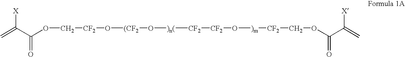
[0068]A polyfluoropolyether compound according to Formula 1A, D20-DA diacrylate, was prepared by the following procedure. A solution of FLK-D20 Diol purchased from Solvay Solexsis (Thorofare, N.J.) (10 gr, 0.005 mol, 1 eqv.) and BHT (1 wt % FLK-D20 0.001 gr) in anhydrous THF (100 ml) was allowed to stir in a 3-neck round bottom reaction flask (250 ml) equipped with a dropping funnel, thermometer, condenser and N2 purge adapter. The reaction flask was cooled down to 0° C. using an ice-water bath. Triethylamine (1.948 gr, 0.0193 mol, 3.85 eqv.) was added dropwise to the solution of FLK-D20 Diol in THF over a 15 minute period. The reaction was maintained at 0° C. A second dropping funnel charged with acryloyl chloride (1.585 gr, 0.0185 mol, 3.5 eqv.) was added dropwise to the solution over a 60 min period. The temp...

example 2

[0077]The following example demonstrates the preparation of a stamp made of a polyfluoropolyether composition with a non-fluorinated photoinitiator.

[0078]The polyfluoropolyether compound, D20-DA diacrylate, was prepared as described in Example 1. The plate composition was prepared by mixing 1 weight % of a non-fluorinated photoinitiator, Darocur 4265, (from Ciba Specialty Chemicals, Basel, Switzerland) illustrated below with the D20-DA. Darocur 4265 is a 50 / 50 mixture of the two structures shown in (a) and (b). The mixture was stirred for 24 hours at room temperature.

[0079]The non-fluorinated photoinitiator was immiscible in the PFPE pre-polymer compound, rendering an non-homogenized mixture. The non-homogenized mixture was then used to make PFPE stamp following the procedure described in Example 1.

[0080]The relief surface of the stamp was characterized by optical micrograph. The micrograph showed good 10 micron dot and line features and many bubbles. The bubbles were defects in som...

examples 3 and 4

[0082]The following examples demonstrate the difference in dimensional stability of stamps prepared with and without a support.

[0083]Both stamps were prepared using a 4 inch (10.16 cm) Silicon (Si) wafer as a master since it provided a highly flat and uniform surface.

[0084]The stamp of Example 3 was prepared according to Example 1, except that the stamp did not include the Melinex® 561 polyester support. The layer was exposed (through the side opposite the master) in a nitrogen box for 10 min at the I-liner wavelength of 365 nm. The thickness of the cured stamp was about 1.5 mm. The layer cured to form a stamp without a support (i.e., freestanding stamp) but delaminated from the master during the curing process and was largely deformed.

[0085]The stamp of Example 4 was prepared according to Example 1, except that the stamp included a support. After the mixture was poured onto the master, a 5 mil Melinex® 561 polyester support having the adhesive layer as described in Example 1 was ap...


PUM

PropertyMeasurementUnit
thicknessaaaaaaaaaa
thicknessaaaaaaaaaa
wavelengthsaaaaaaaaaa

Abstract

The invention pertains to a printing form precursor and a method for preparing a stamp from the precursor for use in soft lithographic applications. The printing form precursor includes a composition layer of a fluorinated compound capable of polymerization upon exposure to actinic radiation and a flexible support transparent to the actinic radiation adjacent the composition layer.

Description

BACKGROUND OF THE INVENTION[0001]1. Field of the Invention[0002]This invention pertains to a printing form precursor, and a method for forming a stamp having a relief structure from the printing form precursor, and in particular, a printing form precursor for forming a stamp having a relief surface for use in microfabricating electronic components and devices.[0003]2. Description of Related Art[0004]Soft lithography shares a common feature of using a patterned elastomer block as a stamp, mold, or mask to generate micropatterns and microstructures. Soft lithography encompasses several techniques of using the elastomer block with a patterned relief structure to generate the micro patterns and structures, including microcontact printing (μCP), replica molding (REM), embossing, micro transfer molding (μTM), micromolding in capillaries (MIMIC), solvent-assisted micromolding (SAMIM), and phase-shift photolithography.[0005]The stamp utilized in soft lithography is most often formed of an e...

Claims


Application Information

Patent Timeline
Patent Type & Authority Applications(United States)
IPC IPC(8): B41N3/00B81C99/00
CPCB29C35/0888B29C2035/0833B81C99/009Y10T428/24479B82Y40/00G03F7/0002B82Y10/00G03F7/00G03F7/20
Inventor PETRUCCI-SAMIJA, MARIABLANCHET, GRACIELA BEATRIZBLOMQUIST, ROBERTLEE, HEE HYUN
Owner EI DU PONT DE NEMOURS & CO
Why Eureka
Try Eureka