Method of manufacturing electrolytic capacitor and electrolytic capacitor

a manufacturing method and electrolytic capacitor technology, applied in wound capacitors, fixed capacitors, capacitor dielectric layers, etc., can solve the problems of large operation complexity, considerable complexity in the cathode draw-out method, and relatively small capacitance of capacitors, etc., to achieve excellent voltage proofing properties, reduce leakage current, and facilitate manufacturing

Active Publication Date: 2008-01-03
SANYO ELECTRIC CO LTD +1
View PDF3 Cites 44 Cited by
  • Summary
  • Abstract
  • Description
  • Claims
  • Application Information

AI Technical Summary

Benefits of technology

[0011]The present invention has been made to solve the problems as described above, and an object of the invention is to provide a method of manufacturing an electrolytic capacitor that can be manufactured more easily as compared with the conventional one, that is excellent in voltage proofing properties and that has a smaller leakage current, and to provide an electrolytic capacitor obtained by the manufacturing method.

Problems solved by technology

Such capacitors, however, have a relatively small capacitance.
This method, namely the cathode draw-out method is considerably complicated as compared with the method impregnating, with an electrolytic solution, a capacitor element including an anode foil on which a chemical conversion coating film is formed and an opposite cathode foil that are wound or rolled with a separator therebetween, which is a method of manufacturing a so-called wound electrolytic capacitor.
However, it is operationally complicated and difficult to form an electrically conductive polymer layer within a wound capacitor element using the electrolytic polymerization or vapor phase polymerization method.
However, it is difficult to wind the chemical conversion coating film and the electrically conductive polymer layer without damage to them and to accordingly form a wound electrolytic capacitor.
Therefore, the methods have a problem that the chemical conversion coating film is damaged and the chemical conversion coating film has a relatively large number of defects.
Another problem is that the additional step of washing to remove the non-reacted monomer and oxidizing agent is required after the chemical oxidation polymerization, and thus the method is complicated.
The method, however, has the problem that the electrically conductive polymer enters the inside of defects present in the chemical conversion coating film on the anode since the soluble conductive polymer is dissolved in the solvent, so that short-circuiting of the electrolytic capacitor is likely to occur and thus the voltage proofing properties are relatively poor.

Method used


Image

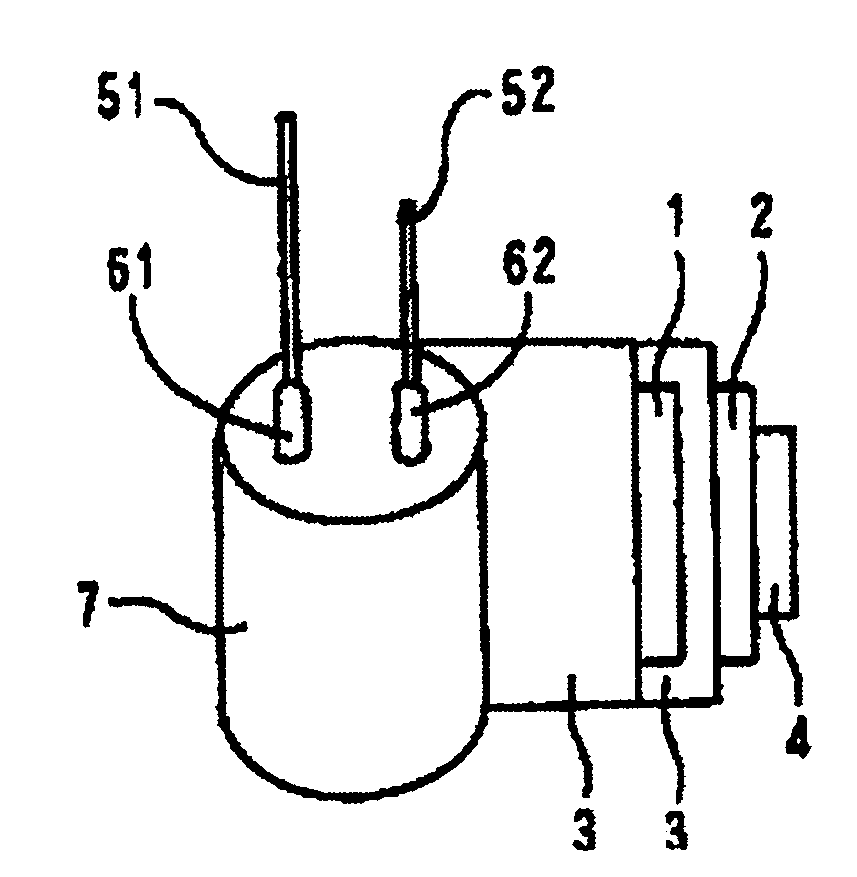
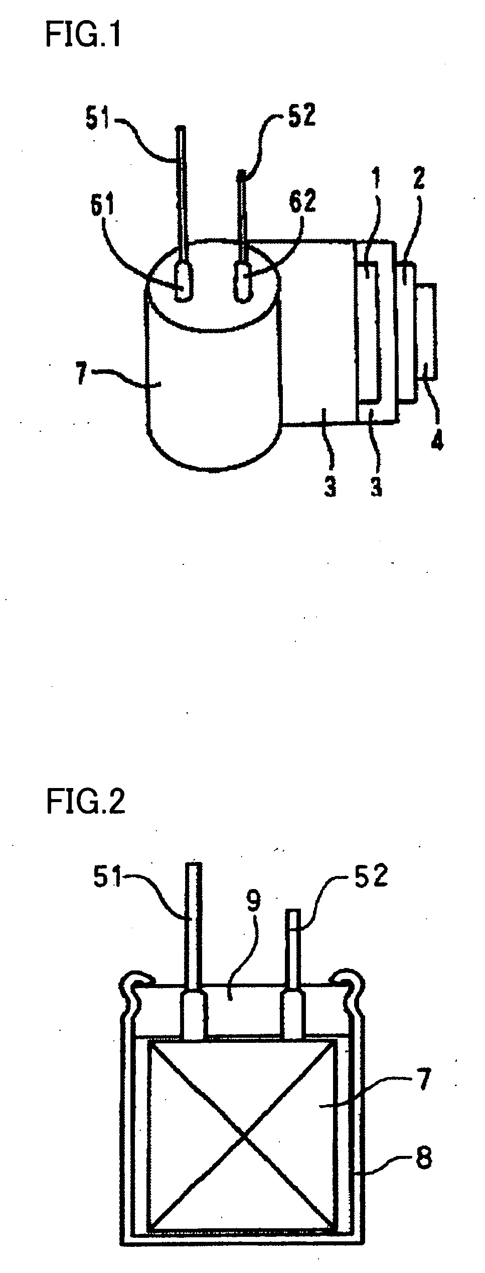
  • Method of manufacturing electrolytic capacitor and electrolytic capacitor
  • Method of manufacturing electrolytic capacitor and electrolytic capacitor

Examples


example 1

[0049]An aluminum capacitor element of the wound type for which the forming voltage (V) used for forming a dielectric coating film was the one as shown in Table 1, which had the dimension in the completed state (the outer dimension of an electrolytic capacitor in the state of being housed in an aluminum casing) of diameter 6.3 mm×height 6.0 mm, and which had a rated voltage of 10 V and a nominal capacitance of 100 μF was immersed in a dispersion containing polyethylenedioxythiophene and water as a solvent (polyethylenedioxythiophene concentration: 8 wt %) at 25° C. for 10 minutes under a high vacuum of 89 kPa so as to attach the dispersion to the dielectric coating film (dispersion impregnation step). While the immersion was performed, a sonicating process was performed. Then, the capacitor element was placed in a dry oven at 125° C. and kept therein for 30 minutes to evaporate the water and thereby form an electrically conductive solid layer (dry step). The dispersion impregnation ...

examples 2-12

[0052]Electrolytic capacitors were each formed by a method similar to that of Example 1 except that the rated voltage and the nominal capacitance, the dimension in the completed state (diameter in mm×height in mm), the forming voltage (V), the electrically conductive polymer and the organic salt contained in the electrolytic solution are those as shown in Table 1. The concentration (wt %) of the electrically conductive polymer in the dispersion and the concentration (wt %) of the organic salt in the electrolytic solution are identical to those of Example 1. For these electrolytic capacitors, the capacitance, ESR, tan δ (loss-angle tangent) and leakage current (LC) were measured. The results as shown in Table 1. Organic salts A, B, C, D shown in Table 1 are respectively triethylamine borodisalicylate, ethyldimethylamine phthalate, mono 1,2,3,4-tetramethylimidazolinium phthalate, mono 1,3-dimethyl-2-ethylimidazolinium phthalate.

example 13

[0058]Measurement of Solid Capacitance Realization Ratio and Confirmation of Effects of Electrolytic Solution:

[0059]Two aluminum capacitor elements of the wound type which had the dimension in the completed state (the outer dimension of an electrolytic capacitor in the state of being housed in an aluminum casing) as shown in Table 2 were each immersed in a dispersion containing polyethylenedioxythiophene and water as a solvent (polyethylenedioxythiophene concentration: 8 wt %) at 30° C. for 10 minutes under a high vacuum of 89 kPa so as to attach the dispersion to the dielectric coating film (dispersion impregnation step). While the immersion was performed, a sonicating process was performed. Then, the capacitor element was placed in a dry oven at 125° C. and kept therein for 30 minutes to evaporate the water and thereby form an electrically conductive solid layer (dry step). The dispersion impregnation step and the dry step were repeated three times in total. Subsequently, one of t...


PUM

PropertyMeasurementUnit
pressureaaaaaaaaaa
pressureaaaaaaaaaa
temperatureaaaaaaaaaa

Abstract

A method of manufacturing an electrolytic capacitor including the following steps as well as an electrolytic capacitor manufactured by the method are provided. The method includes: a dispersion impregnation step of impregnating, with a dispersion containing electrically conductive solid particles or powder and a solvent, a capacitor element having an anode foil with a dielectric coating film formed thereon and an opposite cathode foil that are wound with a separator interposed therebetween; a dry step of evaporating the solvent after the dispersion impregnation step to form an electrically conductive solid layer on a surface of the dielectric coating film; and an electrolytic solution impregnation step of impregnating a gap in the electrically conductive solid layer with an electrolytic solution. Accordingly, an electrolytic capacitor that can be manufactured more easily that is excellent in voltage proofing property and that has a lower ESR and a lower leakage current is provided.

Description

BACKGROUND OF THE INVENTION[0001]1. Field of the Invention[0002]The present invention relates to a method of manufacturing an electrolytic capacitor and to an electrolytic capacitor obtained by the manufacturing method. More specifically, the invention relates to a method of manufacturing a wound electrolytic capacitor and an electrolytic capacitor obtained by the manufacturing method.[0003]2. Description of the Background Art[0004]As digitization of electronic equipment proceeds, it has become required that capacitors used therefor have a smaller size, a larger capacitance and a smaller Equivalent Series Resistance (hereinafter abbreviated as ESR) in a high-frequency range.[0005]As capacitors for a high-frequency range, plastic film capacitors and multilayer ceramic capacitors for example have conventionally been used frequently. Such capacitors, however, have a relatively small capacitance.[0006]An example of a small-sized, large-capacitance and low-ESR capacitor is an electrolyti...

Claims


Application Information

Patent Timeline
Patent Type & Authority Applications(United States)
IPC IPC(8): H01G9/04
CPCH01G9/022H01G9/028H01G9/07Y10T29/417H01G11/48H01G11/56Y02E60/13H01G9/151
Inventor KAKUMA, KENJIHOSOGI, MASAKAZU
Owner SANYO ELECTRIC CO LTD
Why Eureka
Try Eureka