Switching control system to reduce coil output voltage when commencing coil charging

Active Publication Date: 2008-01-17
DELPHI TECH IP LTD
View PDF4 Cites 17 Cited by
  • Summary
  • Abstract
  • Description
  • Claims
  • Application Information

AI Technical Summary

Benefits of technology

[0007]Threshold voltages of coil current switching transistors vary, and the present invention removes error in switching control by dynamically determining the threshold voltage of a power transistor. Implementation of circuitry is thus feasible to minimize dwell timing errors and current conduction overlap in these systems. In an example application, namely an automotive ignition system, the present invention additionally reduces the switching magnitude of coil current at the start of ignition coil charging thereby avoiding an untimely spark event. The collapse of the ignition system IGBT collector voltage is controlled. The reduced collector voltage slew rate results in a reduced secondary coil winding output voltage. The collector slew rate is controlled without requiring voltage divider components or collector voltage feedback systems, thus further reducing costs. Complexity of control circuitry is minimally increased and the present invention provid

Problems solved by technology

This results in a rapid collapse of the voltage across the collector and emitter terminals of the IGBT.
If the voltage at the coil secondary output terminal is sufficiently high in magnitude, a spark may result across the gap of a connected spark plug at an unwanted moment.
The spark event may occur at a time far in advance of the desired ignition time defined by the internal combustion engine piston position resulting in poor engine performance or significant damage.
However, these systems result in either additional system cost associated with the diode or increased IGBT gate voltage control circuitry complexity necessary for implementation of the pulsed turn-on method.
Conventional systems increase system costs by a non-negligible amount.
Since most conventional systems employ control circ

Method used


Image

  • Switching control system to reduce coil output voltage when commencing coil charging
  • Switching control system to reduce coil output voltage when commencing coil charging
  • Switching control system to reduce coil output voltage when commencing coil charging

Examples


Embodiment Construction

[0020]Exemplary embodiments are described with reference to specific configurations. Those of ordinary skill in the art will appreciate that various changes and modifications can be made while remaining within the scope of the appended claims. Additionally, well-known elements, devices, components, methods, process steps and the like may not be set forth in detail in order to avoid obscuring the invention. Further, unless indicated to the contrary, the numerical values set forth in the following specification, figures and claims are approximations that may vary depending upon the desired characteristics sought to be obtained.

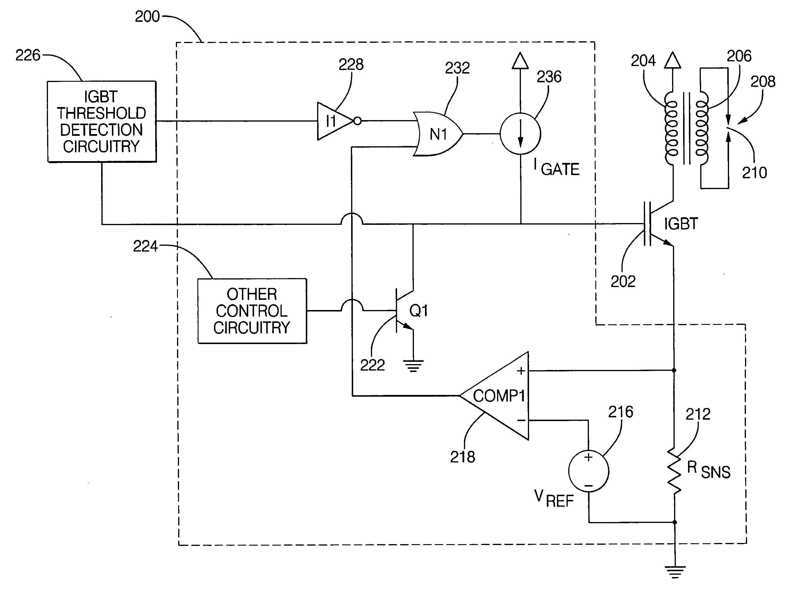
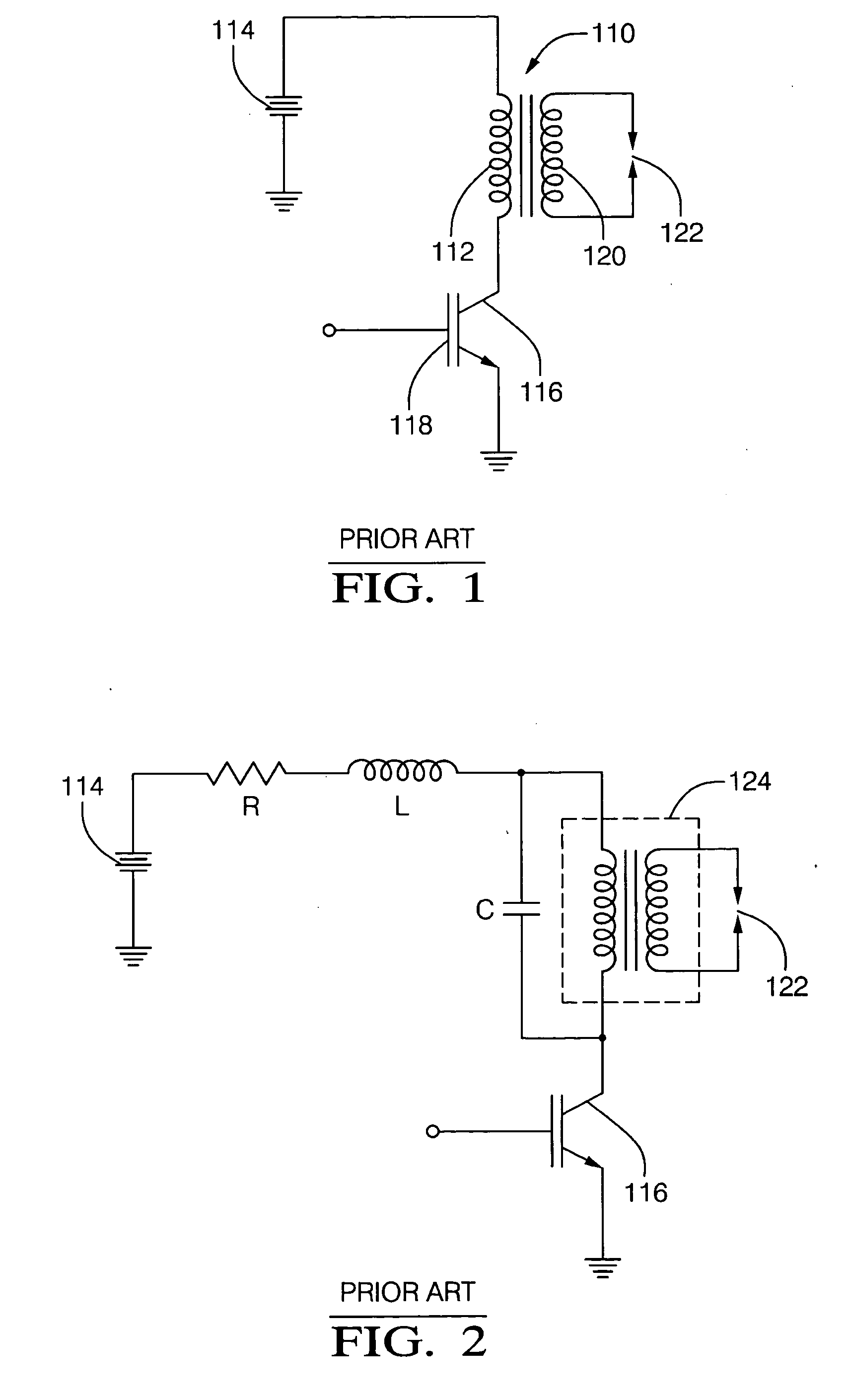
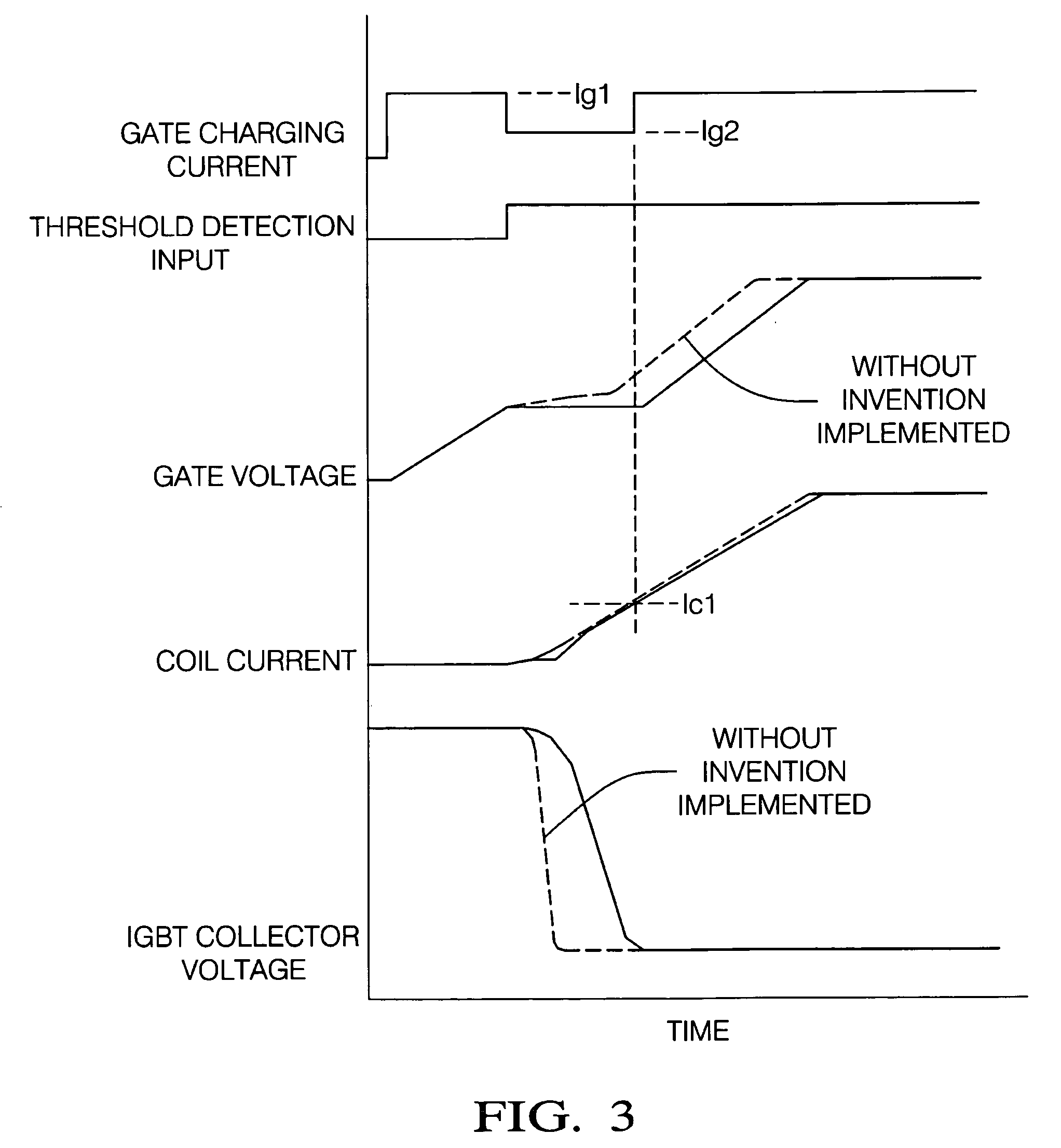
[0021]Power semiconductor devices are commonly used to control the switching of current through systems including automotive ignition systems, solenoid drivers, motor drivers and power regulation systems. Switching control systems are employed to reduce coil output voltage. That is, a rapid voltage collapse rate across terminals of a semiconductor device appears...


PUM


Abstract

A switching control system and method is provided that optimizes switching efficiencies for power switching applications including automotive ignition systems, solenoid drivers, motor drivers and power regulation systems. In an ignition system, a coil current switching magnitude is controlled at the start of ignition coil charging, thereby avoiding an untimely spark event. When the transistor threshold voltage is reached, the collapse rate of the ignition system transistor collector voltage is reduced by reducing the gate charging current. The reduced collector voltage slew rate results in a reduced primary and secondary coil output voltage. After the collector voltage collapses, a continued rapid charge is provided to place the transistor in a hard saturation bias condition. In an aspect, the present invention dynamically determines the threshold voltage of a power transistor. A mirror capacitor substantially matches a transistor gate voltage and a signal is generated when the mirror capacitor voltage proportionally exceeds the transistor gate voltage as a consequence of the transistor reaching a threshold voltage.

Description

FIELD OF THE INVENTION[0001]The invention relates generally to a switching control system, and more particularly to dynamically determining a threshold voltage and controlling a voltage collapse rate of a power transistor to reduce load output voltage.BACKGROUND OF THE INVENTION[0002]Conventional inductive-type automotive ignition systems commonly utilize power semiconductor devices to control the switching of current through ignition coils. Such semiconductor devices are typically controlled so as to switch from an “off” state to a fully saturated “on” state within a short time period, whereby such switching results in the voltage across the ignition coil changing rapidly from substantially zero volts to near battery voltage.[0003]A common type of semiconductor device used in this type of application is an insulated gate bipolar transistor (IGBT). These devices switch large currents while being controlled by the modulation of small voltages on the IGBT's control terminal or gate. P...

Claims


Application Information

Patent Timeline
IPC IPC(8): H01L29/74
CPCF02P3/0456F02P3/053F02P9/002H03K17/567H03K17/14H03K17/30F02P11/00
Inventor KESLER, SCOTT B.
Owner DELPHI TECH IP LTD
Why Eureka
Try Eureka