Multi-focal treatment of skin with acoustic energy

a multi-focal, skin technology, applied in the field of skin treatment, can solve the problems of significant pain, patient discomfort, and significant damage to the epidermis and dermis layers, and achieve the effects of reducing the possibility of injury, high intensity contrast, and reducing the possibility of damage to the underlying bone or other tissue structures

Inactive Publication Date: 2008-01-31
JULIA THERAPEUTICS
View PDF43 Cites 276 Cited by
  • Summary
  • Abstract
  • Description
  • Claims
  • Application Information

AI Technical Summary

Benefits of technology

[0024] In a further aspect of the invention, strong focusing can have an additional benefit as it reduces the possibility of injury caused by ultrasound energy propagating deep into the body. Some areas of facial skin are very thin, e.g., above the cheek bones or forehead. A high intensity contrast between target depth and underlying tissue or organ depth will reduce the possibility of damage to underlying bone or other tissue structures. For example, for applications such as facial applications where bone lie below a relatively thin skin layer, substantial energy penetration at depths greater than 1 mm should be avoided. In other applications, the depth of sensitive underlying structures may be at depths of 2 mm, 3 mm or even 5 mm. For all of these applications, the deep penetration-to-target depth intensity contrast (ratio) is preferably at least about 1:2, more preferably at least about 1:3 or at least about 1:5. For elongated focal regions (e.g., having a length of at least 10 millimeters), the deep penetration-to-target depth intensity contrast (ratio) can be relaxed and is preferably at least about 1:1.2, more preferably at least about 1:1.3 or at least about 1:1.5.
[0025] In yet another aspect of the invention, intensity contrast can be realized through segmentation of the transducer into two or more generally symmetrical parts located approximately on a spherical (or cylindrical) perimeter and aligned is such a way that the resulting additive contribution of this segments creates a wavefront with high intensity contrast. In one embodiment, a monolithic cylindrical transducer can be used with a central area that is acoustically or electrically blocked. More generally, such device designs can create a large synthetic aperture from two or more small aperture emitters. Because the emitters will each individually have a small aperture, the distortion of the wavefront can be much less pronounced.
[0026] In yet another aspect of the invention, the transducer's surface interface to the skin can be designed to be substantially flat. The flatness provides easy and efficient acoustical transmission from waveguide to the skin. Alternatively, grooved surfaces can be employed, with the groove depth preferable less than 500 micrometers, more preferably less than about 100 micrometers.
[0027] The invention is particularly useful for reducing the appearance of human skin wrinkles. Embodiments of the present invention can provide a smoother, rejuvenated appearance of the skin, without adversely damaging the epidermis layer of the skin.

Problems solved by technology

However, the various ablation, heating or freezing techniques that presently are practiced can result in significant damage to the epidermis and dermis layers.
This presents several problems: opportunistic infections can invade the dermis layer and thus complicate or prolong recovery; the procedure can cause a patient significant discomfort and pain; and the skin can appear raw and damaged for a significant period of time (on the order of weeks or months) while the healing process takes place.
All of these side effects are considered undesirable.
However, the use of acoustic energy is often limited by the difficulty in depositing the energy in a tightly focused manner at a target below the skin surface.
While treatment devices with shaped transducers and / or acoustic lenses can be used to concentrate acoustic waves in this manner, the condensing wavefront will be distorted as it cross the boundary from the device to the skin due to the mismatch in acoustic properties of the device's waveguide and the biological tissue.
For example, differences in the speed of sound in the waveguide and skin will cause portions of the collapsing wavefront to lag behind other portions and, thereby, limit the focusing capabilities of such acoustic treatment devices.

Method used


Image

  • Multi-focal treatment of skin with acoustic energy
  • Multi-focal treatment of skin with acoustic energy
  • Multi-focal treatment of skin with acoustic energy

Examples


Embodiment Construction

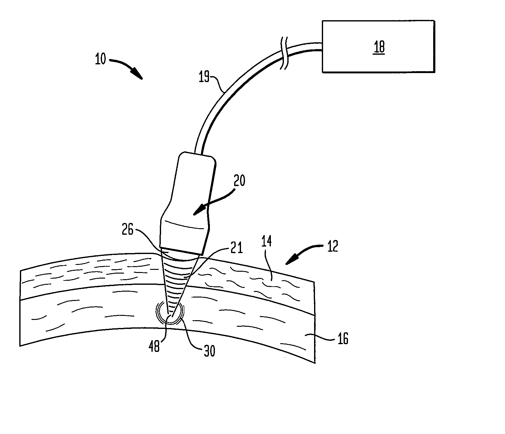
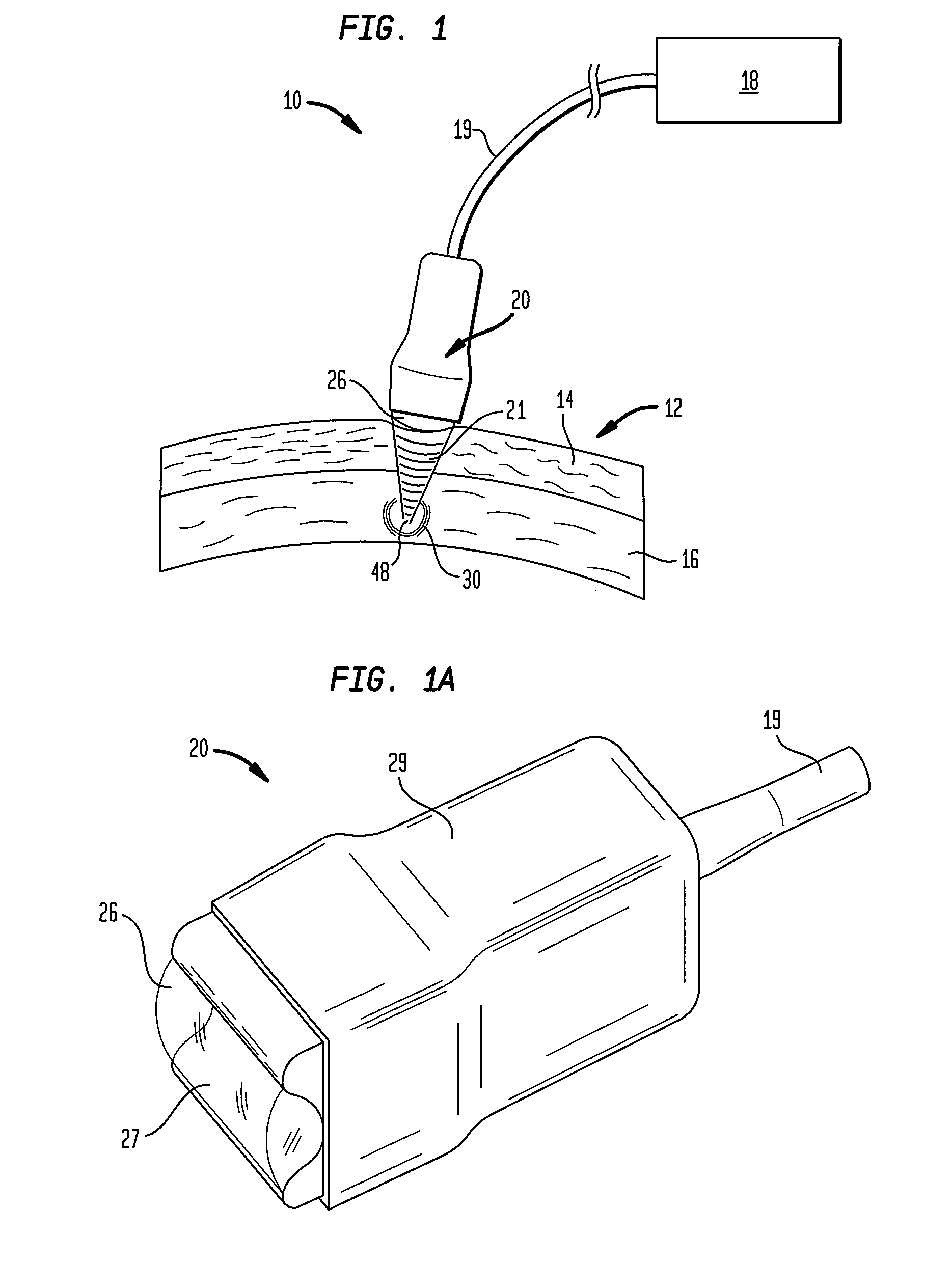
[0068]FIG. 1 generally illustrates an ultrasound generating apparatus 10 that can be used to apply controlled, localized, focused ultrasound to a region of human skin. The apparatus includes a control circuit 18 coupled to handpiece 20 via electrical means 19 which can be a cable or the like. The handpiece includes one or more transducer elements as will be described in more detail below. In response to control signals from control circuit 18, the handpiece 22 generates ultrasound waves 21. Handpiece 22 can have one or more elements, such as piezoelectric elements, that actually produce the ultrasound or similar acoustic waves as well as one or more focusing elements. The handpiece also includes an acoustically-transmitting waveguide 26 having a skin contacting surface, although in some applications it can be desirable to employ an acoustical coupling medium, such as a biocompatible hydrogel between the surface of the waveguide and the skin. Even when a gel is employed, the waveguid...


PUM


Abstract

Methods and apparatus are disclosed for applying acoustic energy to the skin. Acoustic waveguides with elements of varying thickness or shape are disclosed which deliver energy to more than one depth below a surface of the skin substantially simultaneously. The invention is especially useful with devices that focus ultrasound energy by condensing a propagating wavefront. The invention compensates for the mismatch in acoustic properties of the device's waveguide and the biological tissue that typically cause portions of the collapsing wavefront to lag behind other portions and, thereby, limit the focusing capabilities of acoustic treatment devices.

Description

REFERENCE TO RELATED APPLICATIONS [0001] This application is a continuation-in-part of U.S. patent application Ser. No. 11 / 295,700 filed Dec. 6, 2005, which was a continuation-in-part of U.S. patent application Ser. No. 10 / 005,040 filed Dec. 4, 2001, now abandoned, which was a continuation of U.S. patent application Ser. No. 09 / 340,997 filed Jun. 28, 1999, now U.S. Pat. No. 6,325,769, which was a continuation-in-part of U.S. patent application Ser. No. 08 / 998,963 filed Dec. 29, 1997, now U.S. Pat. No. 6,113,559, all incorporated herein by reference. [0002] This application also claims priority to International Patent Application No. PCT / US06 / 46440 filed Dec. 6, 2006, likewise incorporated by reference.BACKGROUND OF THE INVENTION [0003] The technical field of this invention is skin treatment and, in particular, the application of acoustic energy to the skin for cosmetic and / or therapeutic purposes. [0004] Human skin is basically composed of three layers. The outer, or visible layer i...

Claims


Application Information

Patent Timeline
Patent Type & Authority Applications(United States)
IPC IPC(8): A61N7/00
CPCA61B5/01A61B8/0858A61B8/4281G10K11/32A61N7/00A61N7/02G10K11/30A61B2017/00761
Inventor KLOPOTEK, PETER J.LITMAN, PETER E.
Owner JULIA THERAPEUTICS
Why Eureka
Try Eureka