High temperature heating element for preventing contamination of a work piece

a high temperature heating element and work piece technology, applied in the field of high temperature heating, can solve the problems of affecting the quality of workpieces, the heating element itself becoming a source of contamination, and the inability to withstand oxidation or other chemical conditions, so as to achieve accurate determination and closely controlled, the effect of rapid thermal response and faster processing

Inactive Publication Date: 2008-02-21
SOLAICX
View PDF9 Cites 16 Cited by
  • Summary
  • Abstract
  • Description
  • Claims
  • Application Information

AI Technical Summary

Benefits of technology

[0022] The linear configuration of the heating element wire, coupled with the minimized ΔT with the substrate or workpiece, enables temperature of the heating elements and workpiece to be accurately determined and closely controlled, thereby providing a quick thermal response for faster processing and high throughput.
[0023] The foregoing aspects of the invention enable a KANTHAL® or other Fe Cr Al heating element to have a prolonged service life at a given temperature and to be used in higher temperature applications than was previously possible, up to about 1400° C. and above. The ΔT between heating elements and a work piece is minimized, such that the temperature of the workpiece can be closely controlled and is only slightly less than the temperature of the heating elements. Contamination cannot permeate through the aluminum ceramic sheath to degrade the heating element wire, and the heating element does not contaminate the workpiece.

Problems solved by technology

At high temperatures, suitable structural materials for heating elements are limited.
Even heating elements with high temperature structural capacity may be unable to withstand the oxidation or other chemical conditions imposed by high temperature CVD processes.
Heating elements themselves thus become sources of contamination.
Evaporation and / or spalling of metal, such as from a heating element, can become a serious contamination factor in a conventional furnace for semiconductor processing, beginning at about 500° C. Such evaporation is a natural consequence of the vapor pressure of materials.
Vapor pressure varies with materials and is about 100 billion times greater at 1200° C. than at 500° C. Thus, the potential for particulate contamination through out gassing, spalling, or oxidation of a heating element operating at high temperatures is a critical process limitation.
However, such materials are expensive and difficult to use, requiring a disadvantageously high current power supply.
Unfortunately, simultaneous improvement in device fabrication processes, device performance and cost, has been difficult to achieve due to a number of structural and functional limitations in conventional furnaces.
However, conventional heating element coils are characterized by increased resistivity and are prone to oxidation at high temperatures.
In a coil configuration it is difficult to maintain constant resistance at high temperatures.
The spacing between coils cannot be closely regulated at high temperatures, producing temperature variations and hot spots.
When pushed to high operating temperature, hot spots in the coils frequently result in heating element failure.
Furnaces employing conventional elements are often unsuitable for economical and high throughput thin film device fabrication, even at 500° C. process temperatures, let alone operating ranges at 1200° C. and above.
However, this disadvantageously forces the process chamber to operate at high temperature and causes a slow rate of heating and cooling (poor thermal response) when a temperature change is required.
Accordingly, conventional process chamber materials are subject to heat damage, distortion, and may act as a source of contamination, thus resulting in time-consuming maintenance issues and slow processing rates.
Also, the flush engagement of the aluminum oxide ceramic restricts entry of oxygen into the interior of the through holes, such that no additional oxygen is available to react with the Fe Cr Al wire to increase the thickness of the oxide layer.
The spacing of coils cannot be closely regulated and leads to temperature variations.
When pushed to high operating temperature, hot spots in the coils lead to heating element failure.

Method used


Image

  • High temperature heating element for preventing contamination of a work piece
  • High temperature heating element for preventing contamination of a work piece
  • High temperature heating element for preventing contamination of a work piece

Examples


Embodiment Construction

[0034] Overview

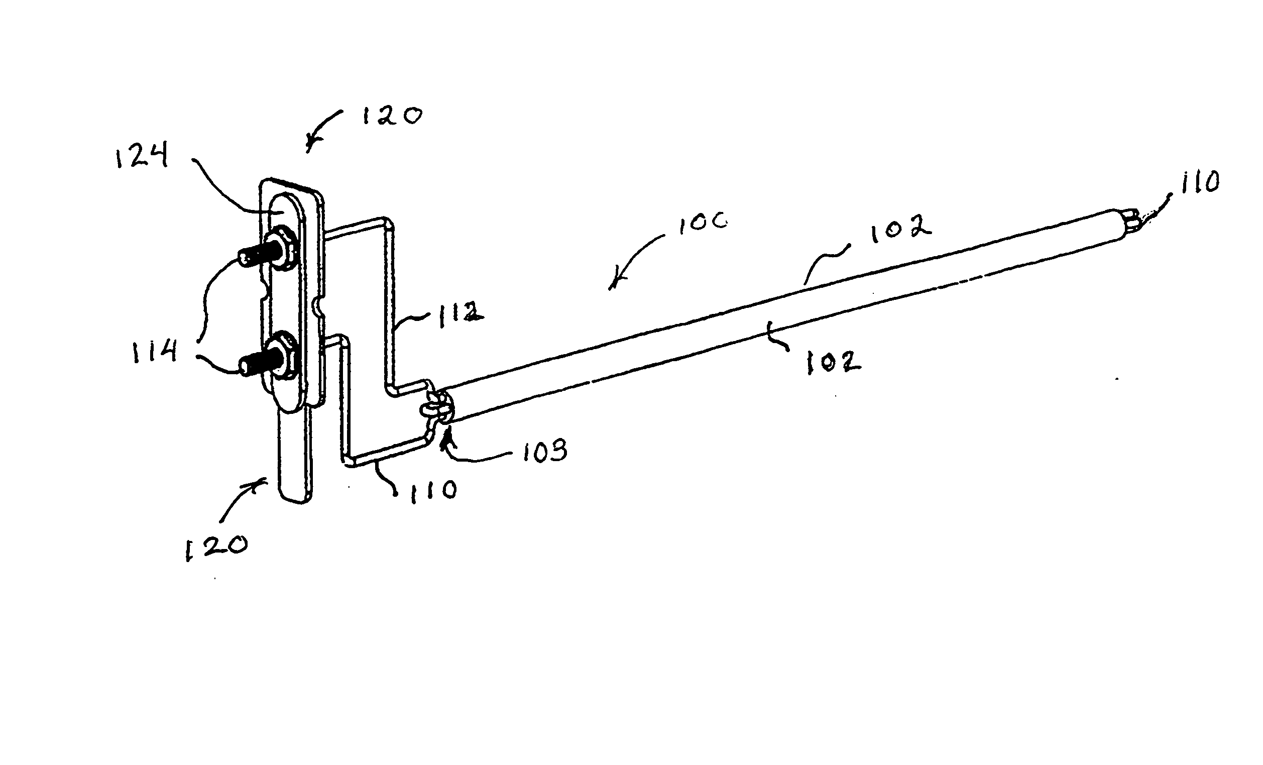
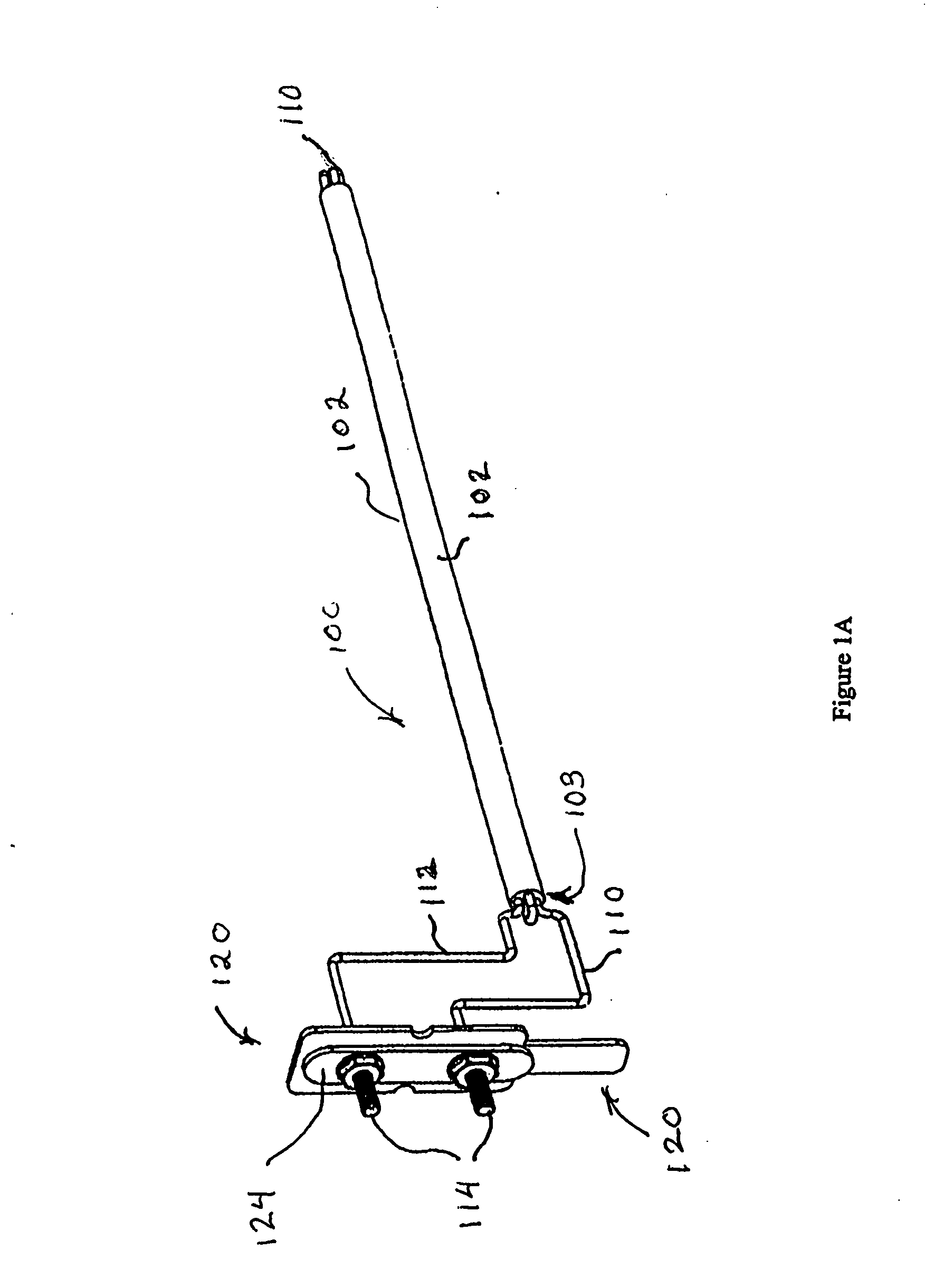
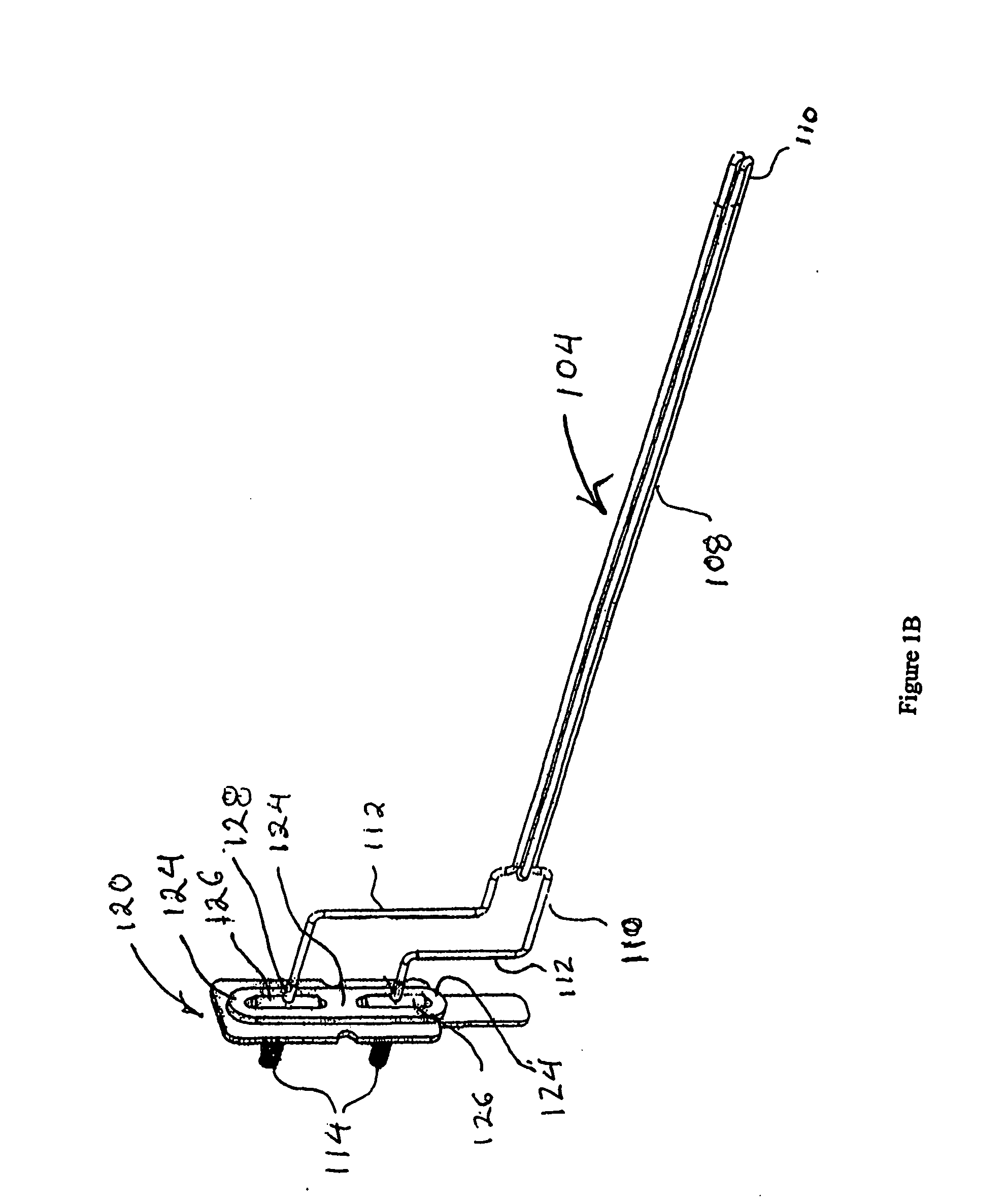
[0035] Referring to FIGS. 1A, and 1B, a heating element assembly 100 in accordance with an aspect of the invention comprises an aluminum oxide ceramic sleeve or sheath 102. Through holes or bores 103 are provided along the longitudinal axis of the ceramic sleeve 102 for protectively enclosing and supporting a heating element wire 104. The heating element wire 104 comprises a main heating portion 108 consisting of an iron chromium aluminum (Fe Cr Al) resistance heating alloy, such as KANTHAL®, a transition portion 110 comprising preferably nichrome, and a terminal portion or end 112 comprising nickel for connection to a source of electric current at power terminals 114. The KANTHAL®, or other resistive heating wire comprises main heating portion 108 having a first diameter for producing a maximum amount of heat within the ceramic sleeve or sheath 102. Optionally, the KANTHAL®, or other resistive heating wire does not need to be a constant diameter, but also may compri...


PUM

PropertyMeasurementUnit
temperaturesaaaaaaaaaa
temperatureaaaaaaaaaa

Abstract

A modular heating element that facilitates removal and replacement without disassembly of a furnace provides a precisely controllable process temperature in the range 1000-1400 degrees centigrade. The configuration of the heating element is linear rather than coiled, and the temperature is monitored directly by measuring the electrical resistance of KANTHAL®, or other like Fe Cr Al wire encased in an aluminum ceramic sleeve that provides mechanical support and seals the heating element wire against oxidation, thereby increasing operational temperature and prolonging service life.

Description

CROSS-REFERENCE TO RELATED APPLICATION [0001] This patent application is a continuation in part of U.S. Ser. No. 10 / 772,188, filed Feb. 3, 2004.BACKGROUND [0002] 1. Field of the Invention [0003] The field of the invention generally relates to heating apparatus. In particular, the field of the invention relates to a heating element for providing contamination free processing of a substrate or workpiece at elevated temperatures, wherein temperature differences between the heating element and a substrate or workpiece are minimized. The heating element has a modular, feed-through configuration that enables it to be inserted directly into a process chamber from the exterior of a furnace for ease of removal and replacement. [0004] 1. Background of Related Art [0005] The manufacture of semiconductor devices requires the deposition of thin dielectric films upon semiconductor wafers at high working temperatures. The most commonly used process is chemical vapor deposition (CVD), using precurs...

Claims


Application Information

Patent Timeline
Patent Type & Authority Applications(United States)
IPC IPC(8): H05B1/00C23C16/00C23C16/46F27B5/04F27B5/14F27B5/18F27B9/04F27B9/06F27B9/20F27B9/36F27B17/00F27D11/02F27D99/00H01L21/00
CPCC23C16/4411C23C16/46F27B5/04F27B5/14F27B5/18F27B9/045H01L21/67109F27B9/20F27B9/36F27B17/0025F27D11/02F27D99/0006F27B9/062H05B3/44H05B3/64F27B9/04F27B9/06F27B17/00F27D99/00
Inventor GRALENSKI, NICHOLAS
Owner SOLAICX
Why Eureka
Try Eureka