
Electroconductive Resin Composition, Production Method and Use Thereof

Inactive Publication Date: 2008-05-01
SHOWA DENKO KK
View PDF11 Cites 18 Cited by
  • Summary
  • Abstract
  • Description
  • Claims
  • Application Information

AI Technical Summary

Benefits of technology

[0014]The present invention solves the above conventional problems and provides an electroconductive resin composition prepared by dispersing every carbon fiber filament as uniform as possible in resin with a smaller amount of electroconductive filler than in conventional method, so that the resin composition can obtain electroconductivity as high as or higher than that of conventional resin compositions, to thereby effectively form an electroconductive network, and production method thereof.
[0015]In order for the resin composition to obtain electroconductivity as high as or higher than that of conventional resin compositions with a smaller amount of electroconductive filler, it is important to prevent carbon fiber filaments from three-dimensionally tangling with each other by controlling the composition and concentration of raw materials of the filler and further controlling the concentration of vapor grown carbon fiber in the production process. On the other hand, the present inventors have found out that in mixing with the resin, it is important to (1) suppress the shearing force in the process of mixing the resin with the electroconductive filler to thereby reduce breaking of filaments as much as possible and to (2)prevent the electroconductive filler from excessive diffusing in the matrix resin in kneading process to thereby form and maintain a network structure necessary for exhibiting electroconductivity.
[0016]The present inventors have studied on properties of filler and kneading method and found out that, by not allowing the filler to remain in agglomerate in the electroconductive resin composition, the resin composition, which effectively forms an electroconductive network, can be imparted with high electroconductivity with addition of a small amount of filler. Further, the inventors have confirmed that reduction in the blending amount of the carbon fiber and uniform dispersion of the carbon fiber lead to prevention of reduction in mechanical strength inherent in the resin.
[0035]According to the present invention, since electroconductivity can be expressed by addition of a small amount of carbon fiber, fluidity of the resin can be maintained without deteriorating mechanical properties of the matrix resin. Thus, an electroconductive resin composition having good surface smoothness, dimension accuracy and gloss is provided.

Problems solved by technology

The filament diameter of polyacrylonitrile carbon fiber (PAN), pitch carbon fiber, cellulose carbon fiber and the like, which are prepared by carbonizing conventional organic fiber through heat treatment under an inert atmosphere, is relatively large, from 5 to 10 μm, and the electroconductivity of these fibers is not so good.
As a result, there are problems of distortion of formed products caused by anisotropy in shrinkage and considerable roughness of formed product surface caused by carbon fiber filaments emerging in the surface.
For the above reasons, resin composition containing carbon fiber derived from organic fiber was considered as unsuitable for precise molding where resin which is highly insulative is imparted with electroconductivity in order to dissipate static electricity and dimensional accuracy is required, and for molding for electronic components where good surface smoothness without a scratch due to contact with cases is required.
However, the pieces of the agglomerates cannot be further reduced to finer ones by kneading process using a normal extruder and therefore, without addition of a large amount of filler, an electroconductive network cannot be formed.

Method used


Image

  • Electroconductive Resin Composition, Production Method and Use Thereof
  • Electroconductive Resin Composition, Production Method and Use Thereof

Examples


example 1

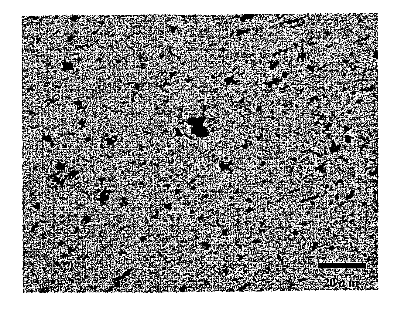
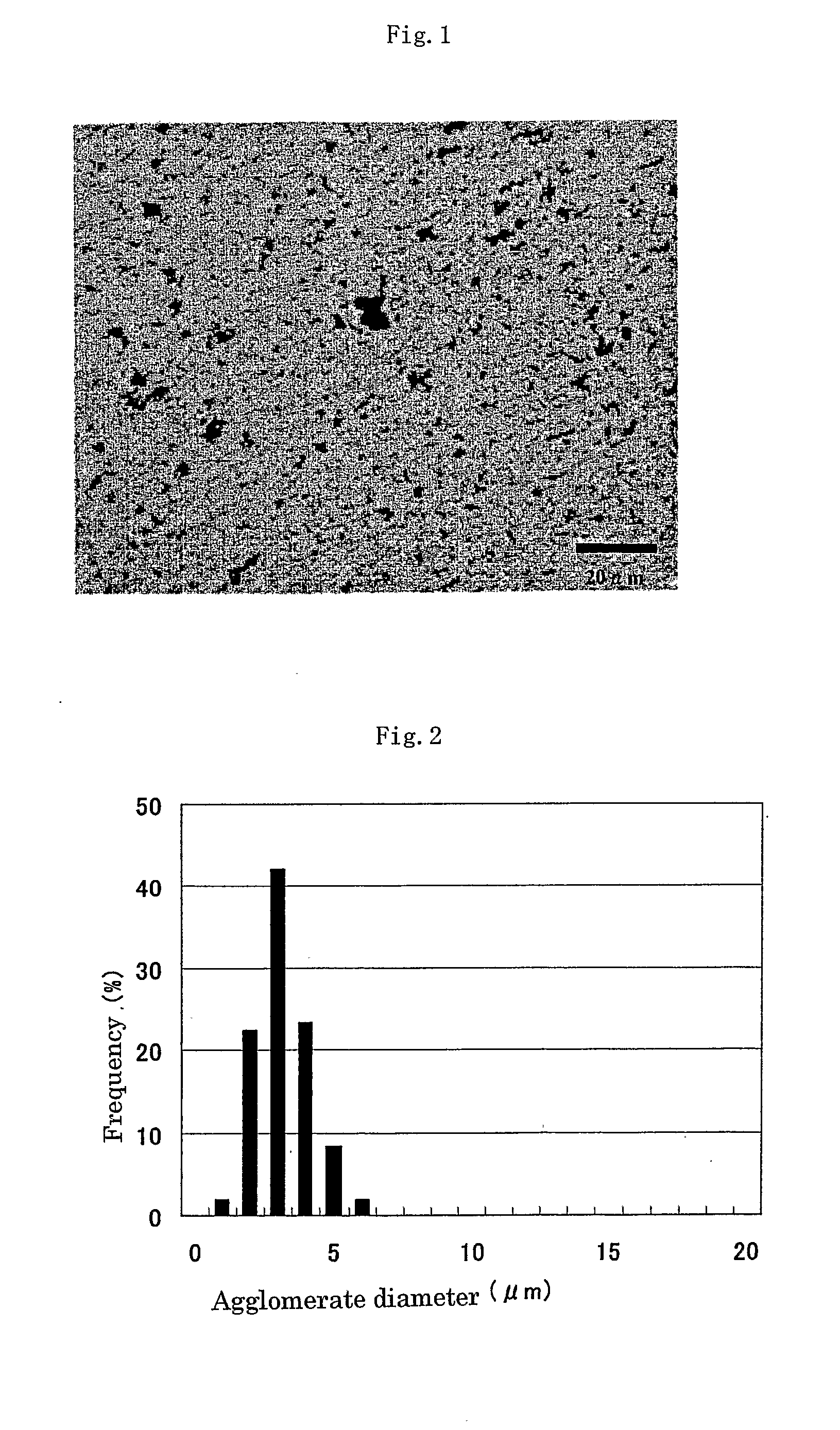
[0100]90 mass % of polycarbonate resin (Iupilon H4000 manufactured by Mitsubishi Gas Chemical Company, Inc.) and 10 mass % of carbon fiber 1 were molten-kneaded at 240° C. and 80 rpm by using a Labo-Plastmill (manufactured by Toyo Seiki Co., Ltd.) for 10 minutes (mixing energy: 850 MJ / m3) and then molded into a plate of 10 mm×10 mm×2 mmt by using a 50 t thermoforming device (manufactured by Nippo Engineering Co. Ltd.) under the condition of the temperature of 250° C., the pressure of 200 kgf / cm2 and the time of 30 seconds, to thereby obtain composite 1. The optical micrograph of a cross section of the plate is shown in FIG. 1 and the analysis result of the aggregate diameter in the micrograph is shown in FIG. 2.

example 2

[0101]Polycarbonate resin (Iupilon H4000 manufactured by Mitsubishi Gas Chemical Company, Inc.) and carbon fiber 2 were kneaded (mixing energy: 950 MJ / m3) in the same manner as in Example 1 and then molded to thereby obtain composite 2.

example 3

[0102]Polycarbonate resin (Iupilon H4000 manufactured by Mitsubishi Gas Chemical Company, Inc.) and carbon fiber 3 were kneaded (mixing energy: 820 MJ / m3) in the same manner as in Example 1 and then molded to thereby obtain composite 3.


PUM

PropertyMeasurementUnit
Fractionaaaaaaaaaa
Percent by massaaaaaaaaaa

Abstract

The electroconductive resin composition comprising 1 to 30 mass % of carbon fiber having a hollow structure, an average filament diameter of 50 to 500 nm and an average aspect ratio of 50 to 1000 and 99 to 70 mass % of resin, wherein the volume ratio of carbon fiber agglomerate to one carbon fiber filament constituting the agglomerate in the resin composition (volume of carbon fiber agglomerate / volume of a carbon fiber filament) is 1500 or less according to the invention can be uniformly dispersed in resin without agglomeration and therefore, a good electroconductivity can be achieved by addition of small amount of the composition.

Description

CROSS-REFERENCE TO THE RELATED APPLICATIONS[0001]This is an application filed pursuant to 35 U.S.C. Section 111(a) with claiming the benefit of U.S. provisional application Ser. No. 60 / 611,267 filed Sep. 21, 2004 under the provision of 35 U.S.C. 111(b), pursuant to 35 U.S.C. Section 119(e)(1).TECHNICAL FIELD[0002]The present invention relates to an electroconductive resin composition which can be uniformly dispersed in matrix of resin such as thermoplastic resin, thermosetting resin or photocurable resin without forming agglomerate of electroconductive filler in the matrix.[0003]More specifically, the present invention relates to an electroconductive resin composition and a production process thereof, wherein by using carbon fiber having few branches which is prepared by adjusting the raw material composition and the raw material concentration during the reactions, agglomerate of the carbon fiber can be easily raveled out without breaking filaments on mixing with resin and a three-d...

Claims


Application Information

Patent Timeline
IPC IPC(8): H01B1/24C09D7/61C09D7/65
CPCC08J5/042C08K3/04C08K7/06C09D5/24C09J11/04C09D7/1275C09D7/1291C09J9/02C09D7/1266C08K2201/016C09D7/67C09D7/68C09D7/70C09D7/65C09D7/61
Inventor NAGAO, YUJIYAMAMOTO, RYUJI
Owner SHOWA DENKO KK
Learn More