Organic light-emitting compound, organic light-emitting device including the compound, and method of manufacturing the organic light-emitting device

Inactive Publication Date: 2008-05-01
SAMSUNG ELECTRONICS CO LTD
2 Cites 52 Cited by

AI-Extracted Technical Summary

Problems solved by technology

When manufacturing OLEDs using a vacuum deposition process, manufacturing costs may increase due to use of a vacuum system, and it may be difficult to manufacture high-resolution pixels for natural color displays due to a shadow mask.
However, when using solution-coatable materials, the performance (such as, thermal stability and color purity) of the light-emitting molecules, specifically blue light-emitting molecules, is reduced when compared to corresponding vacuum-depositable materials.
Even though the light-emitting molecules of the solution-coatable materials have good performance,...

Method used

[0037]In Formula 2a above, R1 and R2 serve to increase the solubility and amorphous characteristics of the organic light-emitting compound of Formula 2a above to thereby enhance film proccesability. The organic light-emitting compound of Formula 2a above is suitable as a material constituting an organic layer interposed between a first electrode and a second electrode of an organic light-emitting device. The organic light-emitting compound of Formula 2a above is suitable to be used in an organic layer of an organic light-emitting device, in particular, an emitting layer, a hole injection layer, a hole blocking layer, an electron transport layer, or a hole transport layer. The organic light-emitting compound of Formula 2a above may also be used as a host material or a dopant material.
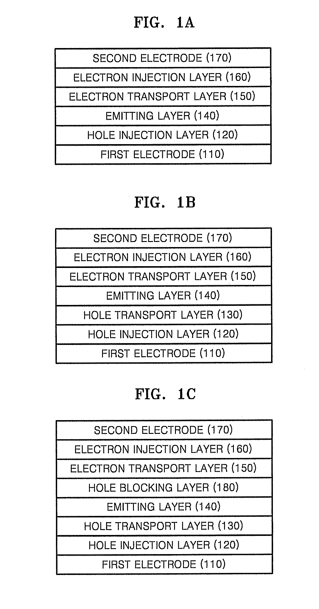
[0071]In a case where the emitting layer 140 includes a phosphorescent dopant, a hole blocking layer (“HBL”) 180 can be formed on a surface of the hole transport layer 130 opposite using a suitable method such as, for example, vacuum deposition, spin-coating, casting, or LB method, in order to prevent the diffusion of triplet excitons or holes into the electron transport layer 150. In the case of for...

Benefits of technology

[0013]In an embodiment, an organic light-emitting...

Abstract

Provided are a compound represented by Formula 1 below and an organic light-emitting device including the same:
wherein X is a C, Si, or Ge atom disubstituted with H or C1-60 organic groups, Ra-Rj are C1-60 organic groups, CY1 is a substituted or unsubstituted C5-C60 aromatic ring or a substituted or unsubstituted C2-C60 heteroaromatic ring, and n is 0 or 1. The use of the compound provides an organic light-emitting device having a low operating voltage and good efficiency and brightness.

Application Domain

Technology Topic

Organic groupPhotochemistry +3

Image

  • Organic light-emitting compound, organic light-emitting device including the compound, and method of manufacturing the organic light-emitting device
  • Organic light-emitting compound, organic light-emitting device including the compound, and method of manufacturing the organic light-emitting device
  • Organic light-emitting compound, organic light-emitting device including the compound, and method of manufacturing the organic light-emitting device

Examples

  • Experimental program(6)

Example

Synthesis Example 1
[0081]A compound 5 (corresponding to Formula 5, above) was synthesized according to Reaction Schemes 1 and 2 below.
Synthesis of Intermediate B
[0082]0.55 g (2.2 mmol) of 9-bromoanthracene was dissolved in THF (5 ml). Then, a solution of 0.6 g (2.2 mmol) of an intermediate A, 75 mg (0.06 mmol) of tetrakis triphenylphosphine palladium (Pd(PPh3)4), and 298 mg (2.2 mmol) of potassium carbonate (K2CO3) in 5 ml of toluene and 2.5 ml of water was added thereto, and the reaction mixture was refluxed for 24 hours. After the reaction was terminated, a solvent was removed by evaporation, and the residue was washed with 100 ml of ethylacetate and 100 ml of water. The organic layer was collected and dried over anhydrous magnesium sulfate. The crude product was purified by silica chromatography to give 0.20 g (yield: 27%) of an intermediate B.
Synthesis of Compound 5
[0083]1.4 g (4.2 mmol) of the intermediate B was dissolved in THF (33 ml), and phenyl magnesium bromide (PhMgBr 1.0 M, 9 ml) was added thereto. The reaction mixture was heated to 70° C. and stirred for one hour. After the reaction was terminated, the resultant solution was washed with 100 ml of water and 100 ml of ethyl acetate. The organic layer was collected, and dried over anhydrous magnesium sulfate and then under a reduced pressure. The resultant solid was dissolved in methylene chloride (42 ml), and trifluorinated boron (0.5 ml) was added thereto. The reaction mixture was stirred for 30 minutes, and methanol (2 ml) was added thereto so that the reaction was terminated. The resultant solution was washed with 200 ml of methylene chloride and 200 ml of water, and the organic layer was collected and dried over anhydrous magnesium sulfate. The crude product was purified by silica chromatography to give 1.1 g (yield: 57%) of the compound 5.
[0084]1H-NMR (CDCl3, 300 MHz, ppm): 8.6-6.9 (m, 22H).

Example

Synthesis Example 2
[0085]A compound 13 (corresponding to Formula 13, above) was synthesized according to Reaction Schemes 3 and 4 below.
Synthesis of Intermediate C
[0086]
[0087]0.73 g (2.2 mmol) of 9,10-dibromoanthracene was dissolved in THF (5 ml). Then, a solution of 0.6 g (2.2 mmol) of an intermediate A, 75 mg (0.06 mmol) of tetrakis triphenylphosphine palladium (Pd(PPh3)4), and 298 mg (2.2 mmol) of potassium carbonate (K2CO3) in 5 ml of toluene and 2.5 ml of water was added thereto, and the reaction mixture was refluxed for 24 hours. After the reaction was terminated, the solvent was removed by evaporation. The residue was washed with 100 ml of ethyl acetate and 100 ml of water, and the organic layer was collected and dried over anhydrous magnesium sulfate. The crude product was purified by silica chromatography to give 0.45 g (yield: 43%) of an intermediate C.
Synthesis of Compound 13
[0088]1.0 g (2.1 mmol) of the intermediate C was dissolved in THF (15 ml), and phenyl magnesium bromide (PhMgBr 1.0 M, 4.5 ml) was added thereto. The reaction mixture was heated to 70° C. and stirred for one hour. After the reaction was terminated, 50 ml of water and 50 ml of ethyl acetate were added thereto. The organic layer was collected, and dried over anhydrous magnesium sulfate and the solvent removed under reduced pressure. The resultant solid was dissolved in methylene chloride (21 ml), and trifluorinated boron (0.5 ml) was added thereto. The reaction mixture was stirred for 30 minutes, and methanol (1 ml) was added thereto so that the reaction was terminated. The resultant solution was washed with 100 ml of methylene chloride and 100 ml of water, and the organic layer was collected and dried over anhydrous magnesium sulfate. The crude product was purified by silica chromatography to give 0.7 g (yield: 48%) of the compound 13.
[0089]1H-NMR (CDCl3, 300 MHz, ppm): 8.7-6.9 (m, 34H).

Example

Synthesis Example 3
[0090]A compound 28 (corresponding to Formula 28 above) was synthesized according to Reaction Schemes 5 and 6 below.
Synthesis of Intermediate D
[0091]1.5 g (4.4 mmol) of 9-bromo-10-phenyl anthracene was dissolved in THF (10 ml). Then, a solution of 1.2 g (4.4 mmol) of an intermediate A, 150 mg (0.12 mmol) of tetrakis triphenylphosphine palladium (Pd(PPh3)4), and 600 mg (4.4 mmol) of potassium carbonate (K2CO3) in 10 ml of toluene and 5 ml of water was added thereto and the reaction mixture was refluxed for 24 hours. After the reaction was terminated, solvent was removed by evaporation. The residue was washed with 200 ml of ethylacetate and 200 ml of water, and the organic layer was collected and dried over anhydrous magnesium sulfate. The crude product was purified by silica chromatography to give 0.85 g (yield: 39%) of an intermediate D.
Synthesis of Compound 28
[0092]1.1 g (2.9 mmol) of the intermediate D was dissolved in THF (18 ml), and phenyl magnesium bromide (PhMgBr 1.0 M, 6 ml) was added thereto. The reaction mixture was heated to 70° C. and stirred for one hour. After the reaction was terminated, the resultant solution was washed with 100 ml of water and 100 ml of ethyl acetate. The organic layer was collected, and dried over anhydrous magnesium sulfate and then concentrated under reduced pressure. The resultant solid was dissolved in methylene chloride (27 ml), and trifluorinated boron (0.3 ml) was added thereto. The reaction mixture was stirred for 30 minutes, and methanol (2 ml) was added thereto so that the reaction was terminated. The resultant solution was washed with 200 ml of methylenechloride and 200 ml of water, and the organic layer was collected and dried over anhydrous magnesium sulfate. The crude product was purified by silica chromatography to give 0.9 g (yield: 62%) of the compound 28.
[0093]1H-NMR (CDCl3, 300 MHz, ppm): 8.7-6.9 (m, 26H).

PUM

PropertyMeasurementUnit
Electric potential / voltage3.4V
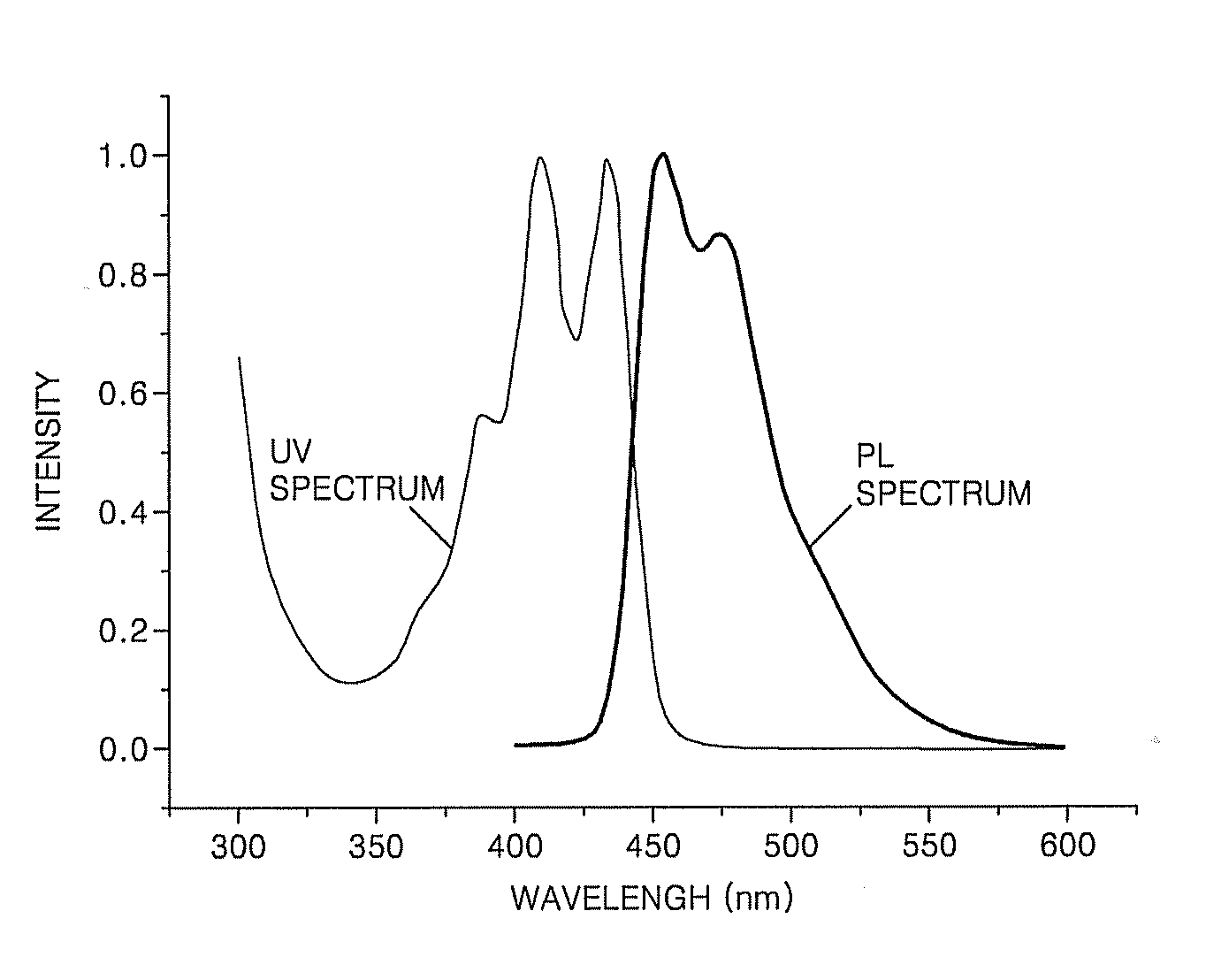
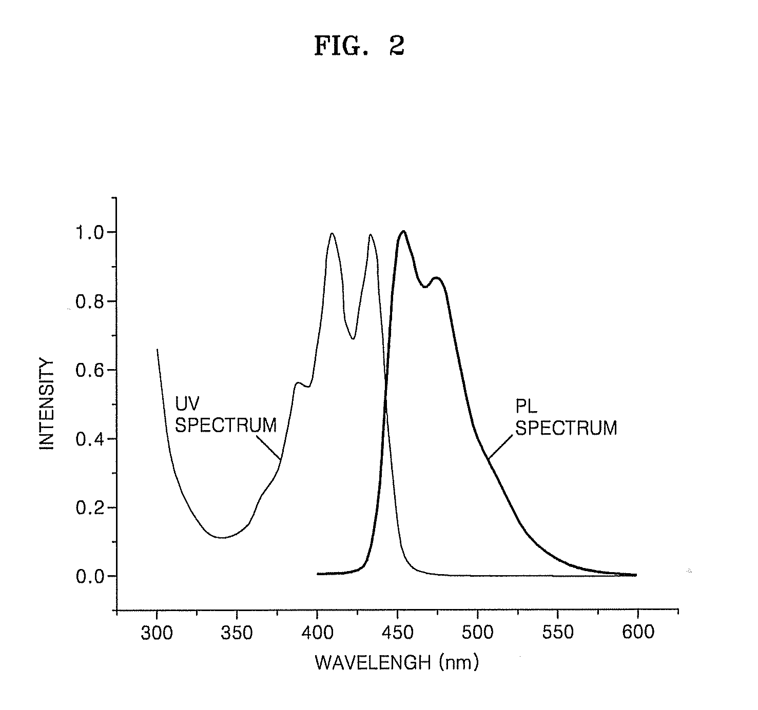
Wavelength410.0nm
Wavelength430.0nm
tensileMPa
Particle sizePa
strength10

Description & Claims & Application Information

We can also present the details of the Description, Claims and Application information to help users get a comprehensive understanding of the technical details of the patent, such as background art, summary of invention, brief description of drawings, description of embodiments, and other original content. On the other hand, users can also determine the specific scope of protection of the technology through the list of claims; as well as understand the changes in the life cycle of the technology with the presentation of the patent timeline. Login to view more.

Similar technology patents

Electrolyte of medium-high voltage aluminum electrolytic capacitor and preparation method of solute thereof

ActiveCN101572187AIncrease the flash voltageGood thermal stabilityCapacitor electrolytes/absorbentsSolventStrong acids
Owner:HUIZHOU CAPCHEM CHEM CO LTD

Halogen-free flame retardant PVC elastic material and preparation method thereof

ActiveCN102443226AGood environmental protection and flame retardancyGood thermal stabilityPlasticizerStabilizing Agents
Owner:JIANGSU XINGHUA RUBBER BELT

Classification and recommendation of technical efficacy words

Why Eureka
Try Eureka