
Electrolyte membrane for polymer electrolyte fuel cell, process for its production and membrane-electrode assembly for polymer electrolyte fuel cell

a technology of electrolyte fuel cell and electrolyte membrane, which is applied in the direction of sustainable manufacturing/processing, conductors, final product manufacturing, etc., can solve the problems of poor stability against radicals, high cost, and poor durability, and achieve excellent durability, excellent resistance to hydrogen peroxide, and stably generating electric power over a long period of time

Inactive Publication Date: 2008-05-22
ASAHI GLASS CO LTD
View PDF8 Cites 21 Cited by
  • Summary
  • Abstract
  • Description
  • Claims
  • Application Information

AI Technical Summary

Benefits of technology

[0017] Since the electrolyte membrane of the present invention has excellent resistance to hydrogen peroxide or peroxide radicals, a polymer electrolyte fuel cell provided with a membrane-electrode assembly having the electrolyte membrane of the present invention is excellent in durability and capable of generating the electric power stably over a long period of time.

Problems solved by technology

Especially when a hydrocarbon membrane is used as the polymer electrolyte membrane, it is poor in the stability against radicals, which used to be a serious problem in operation for a long period of time.
For example, the first practical use of a polymer electrolyte fuel cell was when it was adopted as a power source for a Gemini ship in U.S.A., and at that time, a membrane consisting of sulfonated styrene / divinylbenzene polymer, was used as an electrolyte membrane, but it had a problem in the durability over a long period of time.
However, such a technique is a technique of decomposing formed hydrogen peroxide, and is not one attempted to suppress decomposition of the ion exchange membrane itself.
Accordingly, although at the initial stage, the effect for improvement was observed, there was a possibility that a serious problem would result in the durability over a long period of time.
Further, there was a problem that the cost tended to be high.
However, it has been reported that even with a fuel cell employing an ion exchange membrane made of a perfluorocarbon polymer having sulfonic acid groups, the stability is very high in operation under high humidification, but the voltage degradation is significant in operation under low or no humidification conditions (Non-Patent Document 1).

Method used


Image

  • Electrolyte membrane for polymer electrolyte fuel cell, process for its production and membrane-electrode assembly for polymer electrolyte fuel cell

Examples


example 1

[0046] 300 g of a CF2═CF2 / CF2═CFOCF2CF(CF3)O(CF2)2SO3H copolymer (ion exchange capacity: 1.1 meq / g dry polymer, hereinafter referred to as polymer A), 420 g of ethanol and 280 g of water were charged into a 2 L autoclave, sealed hermetically and mixed at 105° C. for 6 hours by means of a double helical blade to obtain a uniform liquid (hereinafter referred to as “liquid A”). The solid content concentration of the liquid A was 30 mass %.

[0047] 100 g of the liquid A and 0.5 g of cerium carbonate hydrate (Ce2(CO3)3.8H2O) were charged into a 300 mL round-bottomed flask made of glass and stirred at a room temperature for 8 hours by a meniscus blade made of PTFE (polytetrafluoroethylene). Bubbles due to generation of CO2 were generated from the start of stirring, and a uniform transparent liquid composition was finally obtained. The solid content concentration of the obtained liquid composition was 30.1 mass %. The composition was applied to a 100 μm ETFE (ethylenetetrafluoroethylene) sh...

example 2

[0054] 300 g of a CF2═CF2 / CF2═CFOCF2CF(CF3)O(CF2)2SO3H copolymer (ion exchange capacity: 1.24 meq / g dry polymer), 420 g of ethanol and 280 g of water were charged into a 2 L autoclave, sealed hermetically and mixed at 105° C. for 6 hours by means of a double helical blade to obtain a uniform liquid (hereinafter referred to as “liquid B”). The solid content concentration of the liquid B was 30 mass %.

[0055] 100 g of the liquid B and 0.5 g of cerium carbonate hydrate (Ce2(CO3)3.8H2O) were charged into a 300 mL round-bottomed flask made of glass and stirred at a room temperature for 8 hours by a meniscus blade made of PTFE. Bubbles due to generation of CO2 were generated from the start of stirring, and a uniform transparent liquid composition was finally obtained. The solid content concentration of the obtained liquid composition was 30.1 mass %. The composition was applied to a 100 μm ETFE sheet by cast coating with a die coater, preliminarily dried at 80° C. for 10 minutes and dried...

example 3

Comparative Example

[0058] Without adding any substance to the liquid A, an electrolyte membrane was obtained by cast coating. Except for using this electrolyte membrane, a membrane-catalyst layer assembly was obtained and a membrane-electrode assembly was further obtained in the same manner of Example 1. When the membrane-electrode assembly was evaluated in the same manner as in Example 1, the results as shown in Table 1 were obtained.

TABLE 1Output voltage ofoperation under lowOpen circuit voltage (V)humidification (V)After 100InitialInitialhoursEx. 10.720.970.94Ex. 20.750.980.95Ex. 30.760.960.75


PUM

PropertyMeasurementUnit
pressureaaaaaaaaaa
inner diameteraaaaaaaaaa
lengthaaaaaaaaaa

Abstract

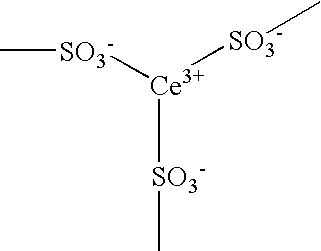
To provide an electrolyte membrane for a polymer electrolyte fuel cell, capable of generating power in high energy efficiency, having high power generation performance regardless of the dew point of the feed gas and capable of generating stable power over a long period of time. A membrane used as an electrolyte membrane for a polymer electrolyte fuel cell, which comprises a cation exchange membrane made of a fluorinated polymer having cation exchange groups and having an ion exchange capacity of from 1.0 to 2.5 meq / g dry polymer, wherein some of the cation exchange groups are ion-exchanged with at least one type of ions selected from the group consisting of cerium ions and manganese ions.

Description

TECHNICAL FIELD [0001] The present invention relates to an electrolyte membrane for a polymer electrolyte fuel cell, whereby the initial output voltage is high, and the high output voltage can be obtained over a long period of time. BACKGROUND ART [0002] A fuel cell is a cell whereby a reaction energy of a gas as a feed material is converted directly to electric energy, and a hydrogen-oxygen fuel cell presents no substantial effect to the global environment since its reaction product is only water in principle. Especially, a polymer electrolyte fuel cell employing a polymer membrane as an electrolyte can be operated at room temperature to provide a high power density, as a polymer electrolyte membrane having high ion conductivity has been developed. Thus, the polymer electrolyte fuel cell is very much expected to be a prospective power source for mobile vehicles such as electric cars or for small cogeneration systems, along with an increasing social demand for an energy or global en...

Claims


Application Information

Patent Timeline
Patent Type & Authority Applications(United States)
IPC IPC(8): H01M8/10C08J5/22
CPCH01B1/122H01M8/1025H01M8/1039Y02E60/521H01M8/1067H01M8/1081H01M2300/0082H01M8/1048Y02E60/50Y02P70/50
Inventor TAYANAGI, JYUNICHIENDOH, EIJIKAWAZOE, HISAO
Owner ASAHI GLASS CO LTD
Learn More