Solid electrolytic capacitor

a solid electrolytic capacitor and capacitor technology, applied in the manufacture of electrolytic capacitors, capacitor dielectric layers, electrical apparatus casings/cabinets/drawers, etc., can solve the problem of high defective fraction of solid electrolytic capacitors, and achieve the effect of reducing defective fraction, low defective fraction, and improving contactability of anode leads and porous bodies

Inactive Publication Date: 2008-06-26
SANYO ELECTRIC CO LTD
View PDF7 Cites 4 Cited by
  • Summary
  • Abstract
  • Description
  • Claims
  • Application Information

AI Technical Summary

Benefits of technology

[0016]Based on this arrangement, it becomes possible to provide an anode lead having an adjusted Vickers hardness of a proper hardness by setting a Vickers hardness of the dielectric layer not more than 20 μm in depth from a surface toward inside of the anode lead, and a solid electrolytic capacitor having a low defective fraction.
[0017]According to a solid electrolytic capacitor of the present invention, the contactability of an anode lead and a porous body can be improved and a defective fraction can be reduced.

Problems solved by technology

Following is a cause of the problem that the defective fraction becomes high on the solid electrolytic capacitor.

Method used


Image

  • Solid electrolytic capacitor
  • Solid electrolytic capacitor
  • Solid electrolytic capacitor

Examples


embodiment 1

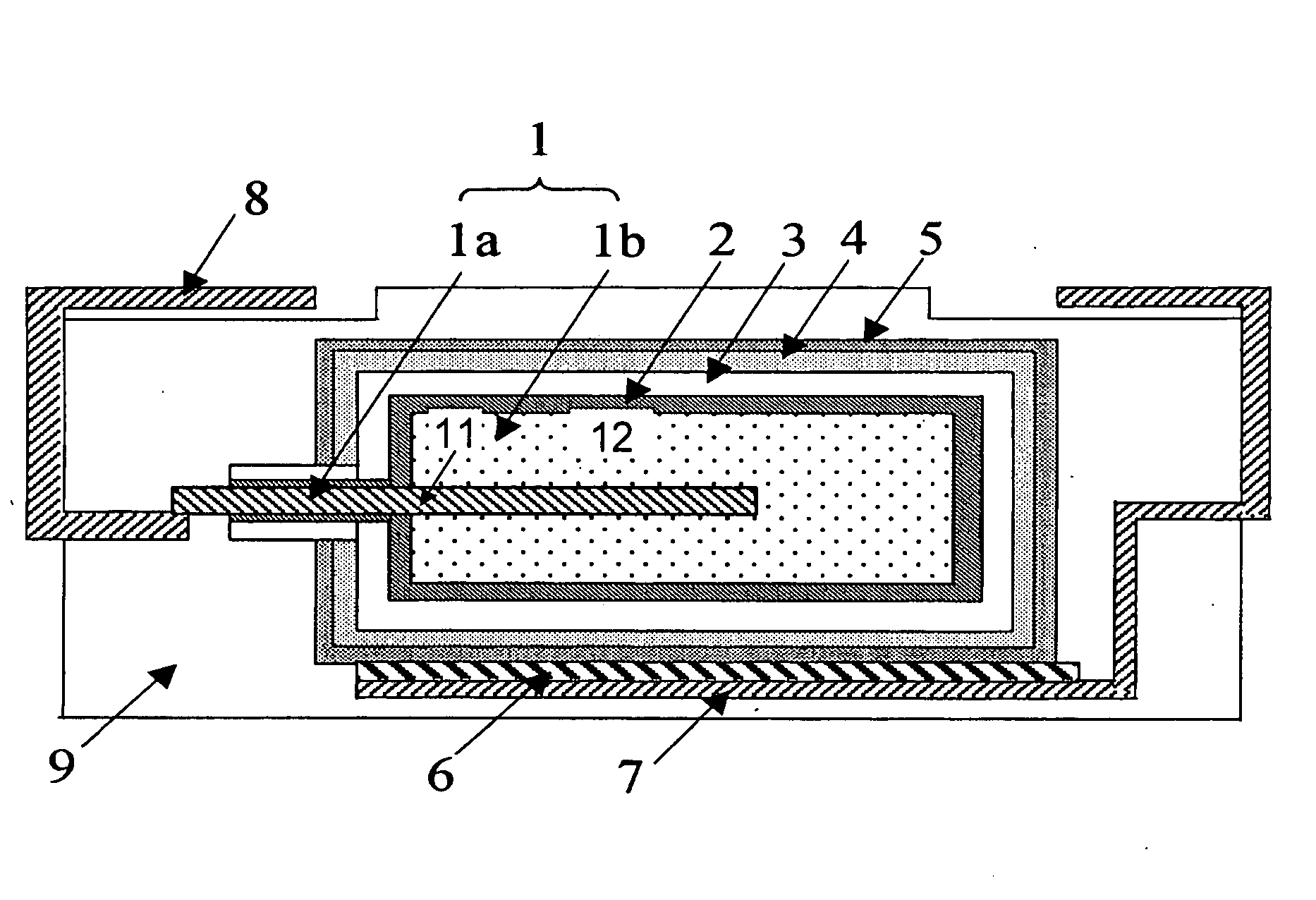
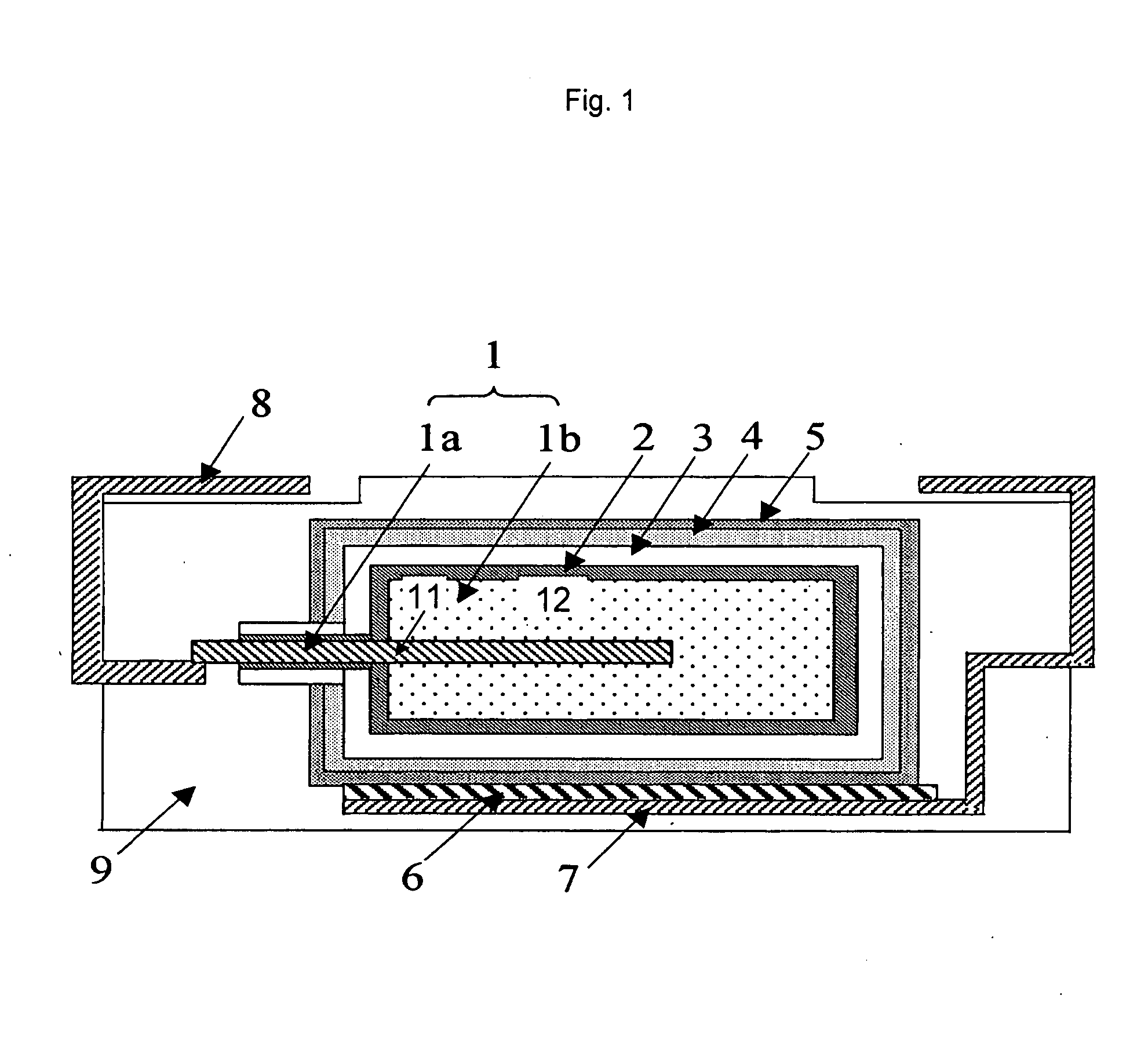
[0042]As an embodiment 1, a sintered porous body 12, metal particles of which have been welded each other by sintering the metal particles having average particle diameter of 2 μm around the anode lead 11 made of niobium (the Vickers hardness at 20 μm from the surface is 30 Hv) with a cooling rate of 0.1° C. / minute in a vacuum is formed. The dimensions of the sintered porous body 12 are about 4 mm in the length, about 3 mm in the width and about 2 mm in the thickness.

[0043]Further, the anode 1 structured by the anode lead 11 and the sintered porous body 12 has been anodized with about 10V of constant voltage for about ten hours in aqueous solution of phosphoric acid of 5 weight-% kept at about 60° C. to form dielectric layer 2 formed by niobium oxide having a thickness of about 25 nm on the surface of the anode 1.

[0044]Next, a conductive high polymer layer 3 composed of polypyrrol is formed on the surface of the dielectric layer 2. Further, carbon paste and silver paste are applied ...

embodiment 2

[0047]In the embodiment 2, the same solid electrolytic capacitor as that of embodiment 1 is formed, except that, as for the anode lead 11 of the embodiment 1, the anode lead 11 structured by niobium (the Vickers hardness is 45 Hv at a point of 20 μm from the surface) with a cooling rate of 0.5° C. / minute is used.

embodiment 3

[0048]In the embodiment 3, the same solid electrolytic capacitor as that of embodiment 1 is formed, except that, as for the anode lead 11 of the embodiment 1, the anode lead 11 structured by niobium (the Vickers hardness is 65 Hv at a point of 20 μm from the surface) with a cooling rate of 1° C. / minute is used.


PUM

PropertyMeasurementUnit
dielectric constantaaaaaaaaaa
outer diameteraaaaaaaaaa
thicknessaaaaaaaaaa

Abstract

An object of the present invention is to provide a solid electrolytic capacitor having a low defective fraction. A solid electrolytic capacitor of the present invention includes an anode structured by an anode lead formed by a valve metal, and porous body of valve metal connected to the anode, and a dielectric layer provided on a surface of the anode wherein a Vickers hardness of the dielectric layer, which is positioned not more than 20 μm in depth from a surface of the anode lead is set 30 Hv-70 Hv.

Description

TECHNICAL FIELD[0001]The present invention relates to a solid electrolytic capacitor having superiority in lowering defective fraction.BACKGROUND OF THE INVENTION[0002]With respect to the solid electrolytic capacitor, Unexamined Japanese Patent Application Publication Nos. 6-151258 and 2004-18966 disclose a solid electrolyte capacitor having a manufacturing method including steps of anodizing an anode formed by valve metal, such as, aluminum, titanium, niobium and tantalum in the aqueous solution of phosphoric acid, forming a dielectric layer on the surface of the anode, providing an electrolytic layer structured by oxide having conductivity or conductive high polymer on the dielectric layer, taking out an anode terminal and a cathode terminal from capacitor element proving a carbon layer and a silver layer onto the electrolyte layer as the cathode terminal, and forming outer case by resin thereafter.[0003]In recent years, the minimization and movement to large capacity of the solid...

Claims


Application Information

Patent Timeline
Patent Type & Authority Applications(United States)
IPC IPC(8): H01G9/04H01G9/15
CPCH01G9/0032H01G9/012Y10T29/417H01G9/15H01G9/07
Inventor NISHIMURA, KOICHINONOUE, HIROSHIUMEMOTO, TAKASHI
Owner SANYO ELECTRIC CO LTD
Why Eureka
Try Eureka