Nanostructured bulk thermoelectric material

a thermoelectric material and nanostructure technology, applied in the direction of thermoelectric device junction materials, thermoelectric device manufacturing/treatment, electrical apparatus, etc., can solve the problems of increasing zt, low-cost thermoelectric devices, and conventional semiconductor device fabrication methods that are unsuitable for manufacturing bulk samples, so as to improve the merit of thermoelectric components

Inactive Publication Date: 2008-07-24
TOYOTA MOTOR CO LTD +1
View PDF5 Cites 108 Cited by
  • Summary
  • Abstract
  • Description
  • Claims
  • Application Information

AI Technical Summary

Benefits of technology

[0009]A thermoelectric composite material comprises two or more components, at least one of which is a thermoelectric material. The thermoelectric composite has a nanoscale structure that enhances the figure of merit of the thermoelectric component.

Problems solved by technology

Increasing ZT is difficult because the three parameters S, σ, and κ are all related to the free carrier concentration and are usually not independent.
However, these approaches do not provide a simple approach to making large-scale, low-cost thermoelectric devices.
Conventional semiconductor device fabrication methods are unsuitable for manufacturing bulk samples, and are often expensive.
In automobiles, about 70 percent of energy derived from fuel is lost to waste heat and engine cooling.
Only a small proportion of energy provided by fuel combustion is used, and a large amount of thermal energy is thrown away.
Recovery of waste thermal energy is a big challenge in automotive industries due to the increasing energy crisis.
However, direct thermal to electric conversion (DTEC) technology currently faces two major challenges: low conversion efficiency and insufficient power density.

Method used


Image

  • Nanostructured bulk thermoelectric material
  • Nanostructured bulk thermoelectric material
  • Nanostructured bulk thermoelectric material

Examples


example 1

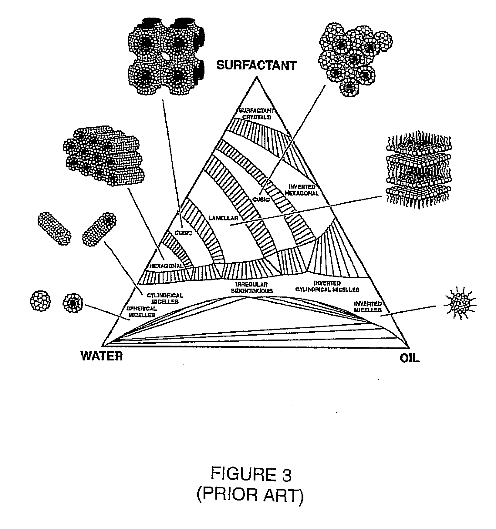
[0080]Porous silica templates were prepared using surfactants as porogens. The surfactants used included PLURONIC surfactant P123 (EO20PO70EO20), F127 (EO100PO70EO100), Brij-58 (C16H33EO20), and cetyltrimethylammoniumbromide (CTAB), where EO and PO designate ethylene and propylene oxide, respectively. The templates were prepared using the surfactant templating process. The average pore diameters of the pores templated with F127, P123, Brij-58, and CTAB were around 12, 9, 6, and 2 nm respectively.

[0081]Bismuth telluride was deposited using a three-electrode deposition circuit. 0.075 M bismuth and 0.1 M telluride dissolved in 1M HNO3 solutions were used as the precursor solution and electrolyte. The deposition was conducted at 0.1 V vs. Ag / AgCl using an Ag / AgCl reference electrode and a Pt counter electrode. The deposition was conducted at room temperature.

[0082]XRD pattern and TEM observation confirmed that Bi2Te3 nanowires with diameter about 6 nm, 9 nm, and 12 nm were deposited wit...

example 2

[0085]A xerogel mesoporous silica was fabricated by using sol-gel technique with PLURONIC surfactant P123 as template. The pore diameter of the as-prepared silica with hexagonal mesostructures was about 9 nm. The precursor solution of Bi2Te3 was prepared by dissolving 0.0225 mol Te and 0.015 mol Bi(NO3)3.5H2O in 150 mL 6 M HNO3 at 60° C.

[0086]5 g powder of xerogel mesoporous silica was added to 7 mL precursor solution. The sample was placed in liquid nitrogen for 3 min. After degassing by vacuum, the sample was warmed to room temperature. Silica powder was separated from precursor solution by centrifugation and then heated at 100° C. in vacuum to remove the solvent. Three and eight cycles of the above process have been conducted in order to increase the loading of bismuth telluride inside the mesoporous materials.

[0087]After infiltration, mesoporous silica with Bi2Te3 precursor was put into tube furnace. With flowing hydrogen, the temperature was increased to 450° C. and kept at thi...


PUM

PropertyMeasurementUnit
diameteraaaaaaaaaa
diameteraaaaaaaaaa
diameteraaaaaaaaaa

Abstract

A thermoelectric material includes a composite having a first electrically conducting component and second low thermal conductivity component. The first component may include a semiconductor and the second component may include an inorganic oxide. The thermoelectric composite includes a network of the first component having nanoparticles of the second component dispersed in the network.

Description

REFERENCE TO RELATED APPLICATION[0001]This application claims priority to U.S. Provisional Patent Application U.S. Ser. No. 60 / 633,918, filed Dec. 7, 2004, the entire content of which is incorporated herein by reference.FIELD OF THE INVENTION[0002]This invention relates to materials having thermoelectric properties and to thermoelectric devices.BACKGROUND OF THE INVENTION[0003]A thermoelectric device can be used to obtain electrical energy from a thermal gradient (for example, a thermoelectric generator using the Seebeck effect), or to generate a thermal gradient from electrical energy (for example, a thermoelectric refrigerator using the Peltier effect). The discussion below is directed to the Seebeck effect, but the general concepts also apply to applications of the Peltier effect.[0004]A typical thermoelectric device is built up from several unicouples, which are typically pairs of thermally conductive p-type (P) and n-type (N) semiconductors. These unicouples are connected elect...

Claims


Application Information

Patent Timeline
Patent Type & Authority Applications(United States)
IPC IPC(8): H01L35/02H01L35/34H01L21/04
CPCH01L35/16H01L35/34H01L35/26H10N10/80H10N10/85H10N10/851H10N10/852H10N10/853H10N10/855H10N10/857H10N10/01
Inventor ZHANG, MINJUANLU, YUNFENG
Owner TOYOTA MOTOR CO LTD
Why Eureka
Try Eureka