Degradable porous implant structure

a porous implant and porous technology, applied in the field of stents, can solve the problems of adverse reactions, thrombosis or inflammation, prior art materials containing significant drawbacks in biocompatibility, functionality or efficacy, etc., and achieve the effect of efficient provision of active agents

Inactive Publication Date: 2008-08-14
CINVENTION AG
View PDF4 Cites 43 Cited by
  • Summary
  • Abstract
  • Description
  • Claims
  • Application Information

AI Technical Summary

Benefits of technology

[0017]There may be a need for an improved implant, e.g. a stent,

Problems solved by technology

However, the introduction of a ‘foreign’ material into a living organism can cause adverse reactions, such as thrombus formation or inflammation.
Prior art materials comprise significant drawbacks in terms of biocompatibility or functionality or efficacy.
Significant drawbacks of prior art solutions are related either to biocompatibility of materials, suitability of the used materials for implant design, and/or reduced usability to provide and release beneficial agents like drugs.
However, although the incorporation of beneficial agents can result in beneficial effects like improved safety or efficacy, after a certain period of time, the implant material itself can cause allergic reactions, chronic inflammation or even thrombosis and other severe complications, e.g. after degradation of the coating or complete elution of the beneficial agents.
To treat this complication, re-intervention and re-vascularisation treatments are necessary that again incur costs for medical care and risks to the patient.
However, surface coatings may have some drawbacks with regard to the controlled release of beneficial agents, because the volume of the incorporated beneficial agent is relatively low compared to the surface area of the stent resulting in a short diffusion length for discharging into the surrounding tissue.
Increasing the thickness of a surface coating may be a solution, but an increase of coating thickness, typically above a range of 3-5 μm, increases the stent wall thickness resulting in reduced flow cross-section of the vessel lumen, and furthermore may increases the profile of the stent resulting in more traumatic deposition of the stent and difficulties in placing them into small vessels.
On the other hand, the use of polymer coatings on stent surfaces can be associated with a higher and significant risk of thrombosis, due to insufficient re-endothelialization of the vessel wall and pertinent presence of less or insufficiently biocompatible material.
Recent clinical studies have also revealed that the use of polymers in drug-eluting stents is one of the ca

Method used


Image

  • Degradable porous implant structure
  • Degradable porous implant structure
  • Degradable porous implant structure

Examples


Embodiment Construction

[0017]There may be a need for an improved implant, e.g. a stent, which may be capable of an efficient provision of an active agent.

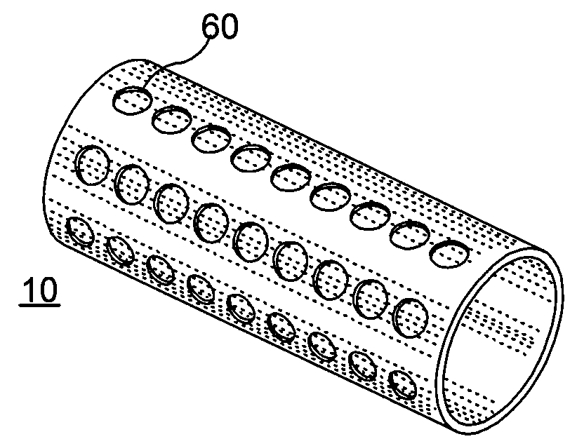
[0018]According to an exemplary embodiment of the present invention, an implant, e.g. a stent, can be at least partially biodegradable and which may have at least one section made of a material having a structure comprising a plurality of material particles, which particles are arranged in a matrix structure embedding a plurality of pores thus forming an open porous structure, whereas the material particles may be joined at contact surfaces to adjacent material particles, wherein an average size of the pores is larger than an average size of the material particles.

[0019]In any exemplary embodiment of the present invention substantially some or all sections of the stent can be made of a material having a structure comprising a plurality of material particles made of a biodegradable material.

[0020]Open porous can mean that, e.g., the pores are interconnect...


PUM


Abstract

Exemplary embodiments of the present invention relate to a stent, and in particular to at least partially biodegradable stent having at least one section made of a material having a particular porous structure.

Description

CROSS-REFERENCE TO RELATED APPLICATION(S)[0001]The present invention claims priority of U.S. provisional application Ser. No. 60 / 889,697 filed Feb. 13, 2007, the entire disclosure of which is incorporated herein by reference.FIELD OF THE PRESENT INVENTION[0002]The present invention relates to a stent, and in particular to an at least partially biodegradable stent having at least one section made of a material having a particular porous structure.BACKGROUND INFORMATION[0003]Implants are widely used as short-term or long-term devices to be implanted into the human body in different fields of application, such as orthopedic, cardiovascular or surgical reconstructive treatments. The ongoing development of medical devices including long term implants, such as articular and intravascular prostheses, and short term implants like catheters, has improved the efficacy of surgical and / or interventional treatments. However, the introduction of a ‘foreign’ material into a living organism can cau...

Claims


Application Information

Patent Timeline
IPC IPC(8): A61F2/06
CPCA61L31/022A61L31/146A61L2300/00A61L31/16A61L31/148
Inventor ASGARI, SOHEIL
Owner CINVENTION AG
Why Eureka
Try Eureka