Safe, Super-efficient, Four-wheeled Vehicle Employing Large Diameter Wheels with Continuous-Radius Tires, with Leaning Option

a four-wheeled vehicle, super-efficient technology, applied in the direction of vehicular safety arrangments, electric devices, propulsion parts, etc., can solve the problems of affecting the ultimate goal of lowering the total cost of ownership, affecting the cost, and automobiles designed for 4-5 occupants, etc., to achieve advanced cornering capability, transfer system, and added driving excitement

Inactive Publication Date: 2008-09-18
BARTILSON BRADLEY WAYNE
View PDF76 Cites 61 Cited by
  • Summary
  • Abstract
  • Description
  • Claims
  • Application Information

AI Technical Summary

Benefits of technology

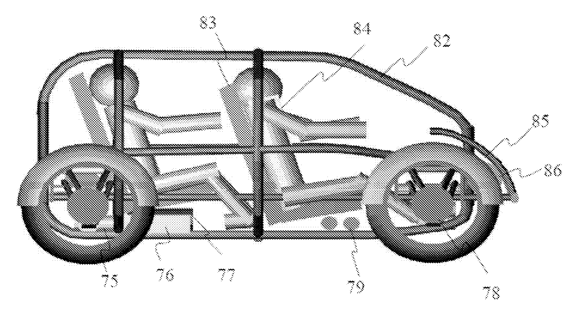
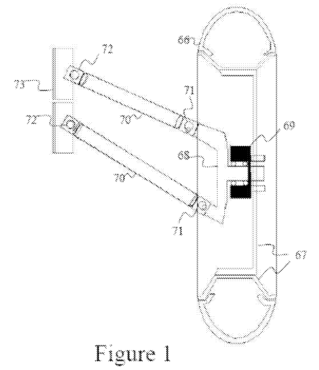
[0043]Another object is to achieve, as a special configuration of the present invention, a 4-wheeled leaning vehicle, to enable advanced cornering capability and added driving excitement.
[0044]An object of the invention is to extract a significant amount of waste energy available from the ICE through higher device (>15%) and transfer system efficiency, and to perform this extraction down to a much lower temperature (<200° C.).
[0045]Another object of this invention is to provide an electrical storage system which accepts high and variable rates of charge transfer, exhibits high efficiency, high reliability over many cycles, and high capacity utilization.
[0046]Another object of this invention is to effect a low-complexity, “no moving parts”, solid-state transfer system, exhibiting low cost, and high reliability.
[0047]Another object of the invention is to create a low-mass design, thereby incurring minimal added weight burden to a high efficiency transportation vehicle.
[0048]Another object of the invention is to reduce or eliminate the requirement for noise abatement from the exhaust system.

Problems solved by technology

Use of lighter-weight materials offer some advantage, however, this impacts cost, negatively impacting the ultimate goal of lower total cost-of-ownership.
Further, automobiles continue to be designed for 4-5 occupants negatively impacting vehicle weight.
The wheels and tires of present 4-wheeled vehicles limit the extent of vehicle weight reduction and suspension options.
However, motorcycles, are market-limited, primarily used for enjoyment riding, as they do not provide a closed occupant configuration to provide additional safety to the occupants and to protect the occupants from the weather elements.
Three-wheeled motorcycle variants with enclosures have been introduced with limited marketability, presumed due to poor experience with 3-wheeled ATVs (all terrain vehicles) and their subsequent forced market removal.
While market savvy, this approach is quite limited in fuel efficiency improvement, in view of the established relationship of fuel consumption to vehicle mass (EPA data: 1 gallon / 100 miles / 900 pounds).
Energy storage in hybrid drivetrains has incurred significant additional mass to the vehicle.
Unfortunately the combination of batteries and ultracapacitors brings about other limitations, as well as added costs, complexity and reduced reliability.
For a series combination of batteries and ultracapacitors, the battery limits the current rate, so little improvement in charge / discharge rate occurs.
When used in parallel, the ultracacapacitors, whose characteristic voltage change is stronger than the battery for a given charge / discharge rate, the battery limits the capacity use.
A pure ultracapacitor storage solution was not envisioned for automobile application, as ultracapacitors are too low in energy storage (<10 W-hr / kg) to accommodate the mass-driven requirements of the current automobile platform.
However, this methodology results in significant underutilization of the capability of the UCS (typically less than 50% as voltage input variations are limited to 2:1 for many devices).
The additions of banks (either battery or UC) bring increased switching components / complexity, efficiency loss, increased weight (reducing vehicle efficiency) and cost.
U.S. Pat. No. 6,265,851 describes an electric vehicle power system for a semiconductor wafer handling application, having ultracapacitors and batteries as parallel sources connected to a source-selecting switch and having said switch direct its output only to a DC-DC converter which serves the motor load, however, this incurs the converter losses when no conversion is necessary.
In the described topologies, all power is continuously directed through a power converter module, with inherent losses and limitations per device sizing.
This approach does not address the inefficient ultracapacitor capacity utilization issue, resulting in extensive burden / cycling of the engine and / or significant oversizing of the ultracapacitor bank.
While low in cost the use of the braking resistor diverts energy, thereby wasting said energy.
The opportunity afforded by improving the thermal efficiency of internal combustion engines (ICE) (commonly 28% for gasoline, 34% for diesel engines) is well understood, however long-standing research and development efforts have not produced marked technical and / or market impacts.
Turbo-charging and ceramic insulation of combustion chamber components have made the most significant impact, however, cost and the extent of efficiency improvement (˜10%), has not led a to significant reduced fuel consumption on a functional work unit basis, and accordingly not impacted the per capita basis.
Exhaust gas turbines with mechanically-connected generators have been presented as alternative, however, cost and efficiency have similarly pre-emptied commercialization.
Thermal-to-Electric devices and systems have also been presented to capture the waste stream energy, however, the device efficiencies for prior thermoelectric and thermionic cases, have been very low (<10%), limiting the use to lesser power applications.
Efficient use of prior devices were also limited to very high temperatures, typically requiring >700° C. The design of the thermal transfer system encapsulating the thermoelectric or thermionic devices have lacked adequate transfer surface and residence time, resulting in reduced energy extraction from the bulk stream.
In the case of transportation vehicles, having proliferated a high-mass (high load) basis contributes to the magnitude of the loss, and increases the magnitude and cost of thermal recovery options.

Method used


Image

  • Safe, Super-efficient, Four-wheeled Vehicle Employing Large Diameter Wheels with Continuous-Radius Tires, with Leaning Option
  • Safe, Super-efficient, Four-wheeled Vehicle Employing Large Diameter Wheels with Continuous-Radius Tires, with Leaning Option
  • Safe, Super-efficient, Four-wheeled Vehicle Employing Large Diameter Wheels with Continuous-Radius Tires, with Leaning Option

Examples


Embodiment Construction

[0076]Vehicle power consumption is expressed as the sum of inertial, rolling, grade, and air drag resistances, accompanied by accessories power usage.

Pload=Pinertia+Ptires+Pgrade+Pdrag+Pacc

Where,

Pinertia=0.5 M[Δv2 / Δt]

Ptires=CπM gv (also stated as the tire rolling friction)

Pgrade=M gv sin(θ) (θ is the grade angle)

Pdrag=0.5ρCDAv3 / 1000

Pacc=Palterator+Pair conditioning

[0077]Inertial, rolling and grade resistance terms dominate power consumption in city driving (typically at least 70% when air conditioning is operating, and up to 90% without air conditioning). Dependent upon grade work associated with a particular geography, these mass-dependent terms commonly comprise 40% of the power load on the highway.

[0078]Underpinning the aforementioned automobile limitations, the current design assumption of a “heavyweight” (2500-4000 pound) vehicle causes designers to select “heavyweight” automobile wheels and tires (typically 40-60 pounds in combined weight). Suspension components are accordin...


PUM


Abstract

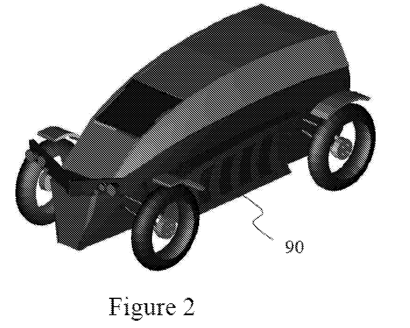
A “super fuel efficient”, safe, low-cost and yet high performance 4-wheeled vehicle is configured with motorcycle wheels and tires having continuous radius tires and of outside diameter (20-26 inches). A special configuration of the invention permits a 4-wheeled vehicle to naturally camber while engaging a corner, or while maneuvering on a slope. Integration of a “short-cycling”, low storage mass hybrid drivetrain into the vehicle, and further, an exhaust heat energy recovery system, secures the efficiency opportunity.

Description

STATEMENT OF RELATED APPLICATIONS[0001]The application is a continuation in part of Bartilson U.S. patent application Ser. No. 11 / 686935 which is a continuation in part of Bartilson U.S. patent application Ser. No. 11 / 68314 filed Mar. 14, 2007, which is a continuation in part of Bartilson U.S. patent application Ser. No. 11 / 613014 filed Dec. 19, 2006.BACKGROUND OF THE INVENTION[0002]The present invention relates to the general area of improved energy efficiency, performance, driving excitement, and safety and of a four-wheeled vehicle.DESCRIPTION OF RELEVANT ART[0003]In the art of higher efficiency transportation vehicles, vehicle weight is known by elementary physics and experience to be the strongest variable influencing fuel consumption. After losing 75% of the combustion energy to waste heat, current vehicles waste 95% of the remaining energy to moving the vehicle mass, resulting in an overall efficiency of just 2% in performing the desired function of moving the occupants. The ...

Claims


Application Information

Patent Timeline
Patent Type & Authority Applications(United States)
IPC IPC(8): B60K6/08B60G21/00B60R19/02B60R21/13B62D21/00B60R19/26B60K1/02
CPCB60G3/20B60G7/02B60G2200/144B60G2300/45B60K6/46Y02T10/92B60R21/13B60R2021/137B62D31/003Y02T10/6217B60K7/0007B62D23/005Y02T10/62
Inventor BARTILSON, BRADLEY WAYNE
Owner BARTILSON BRADLEY WAYNE
Why Eureka
Try Eureka