
Solar Cell Module and Method For Its Production

a solar cell and module technology, applied in the field of solar cell modules, can solve the problems of high cost, large number of individual parts, and often unsuitable methods, and achieve the effect of reasonable and cheap production and excellent heat dissipation

Inactive Publication Date: 2008-09-25
FRAUNHOFER GESELLSCHAFT ZUR FOERDERUNG DER ANGEWANDTEN FORSCHUNG EV
View PDF18 Cites 13 Cited by
  • Summary
  • Abstract
  • Description
  • Claims
  • Application Information

AI Technical Summary

Benefits of technology

[0010]It is therefore the object of the present invention to produce a solar cell module and also a method for the production thereof, with which solar cells can be produced reasonably and cheaply and precisely with respect to manufacturing technology, an excellent heat dissipation requiring to be ensured.
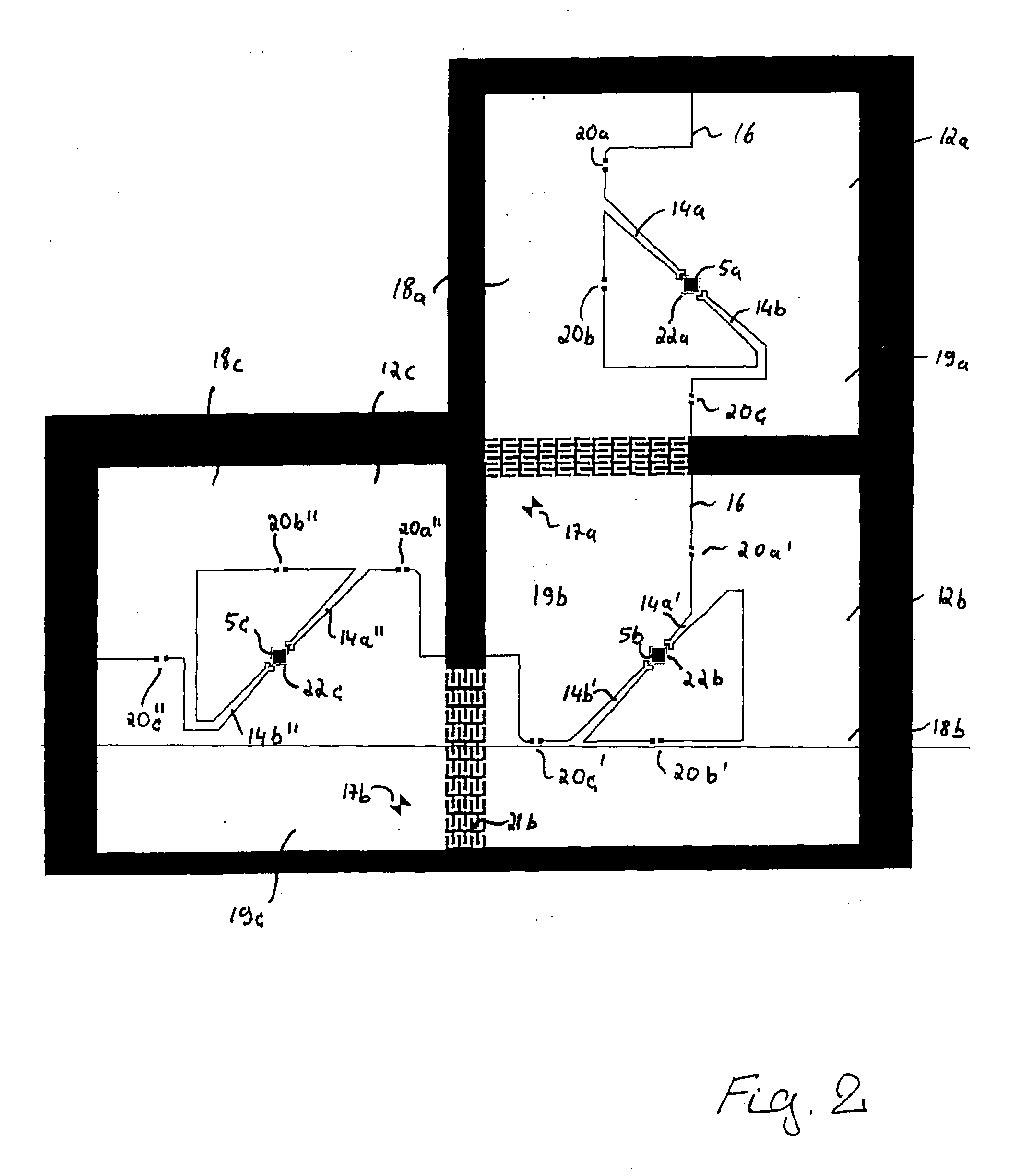
[0016]It is now crucial in the present invention that, during production of the module, individual fully contacted solar cell chips are not manufactured first of all and subsequently positioned individually but rather, in one operating step, the entire module surface is provided with a metal layer, for example a copper layer, which, on the one hand, provides the contacting of the solar cells both with respect to the negative and the positive terminal and, above all, facilitates positioning of the solar cells themselves. For this purpose, a planar, thin, for example 0.01 to 3 mm thick metal substrate, for example a copper foil, is structured by means of a suitable method, such as for example punching or laser beam cutting. This structured metal surface can be connected then to the module base (substrate). It is also possible firstly to apply a metal layer on the module base and thus to produce a laminate, for example a metal foil laminated on glass. The structuring can then be effected subsequently directly on the substrate. The structuring itself is possible as a result of all the conventional measures, such as for example etching methods or also laser machining.
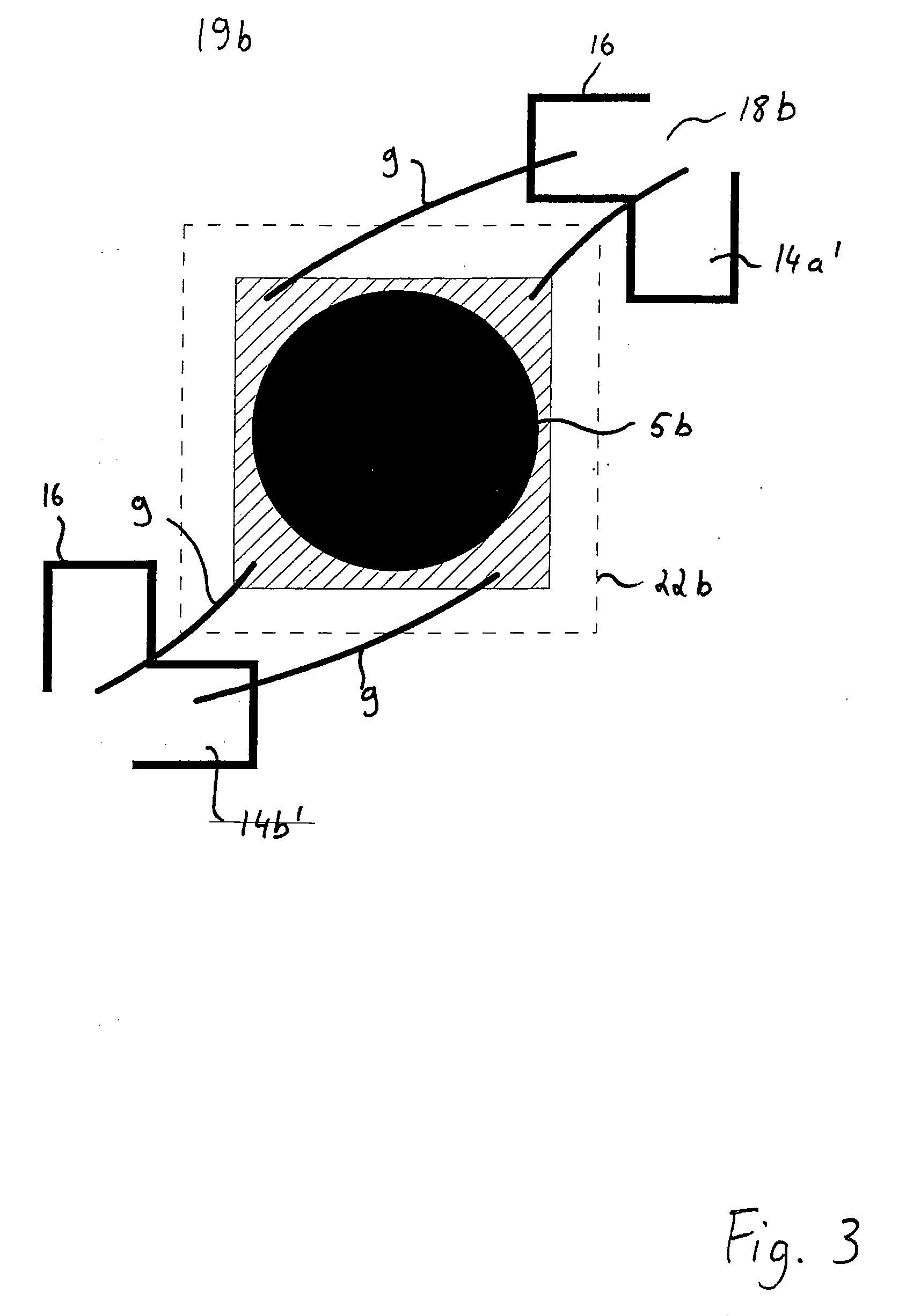
[0018]With a solar module according to the present invention, the electrical contacting of the solar cells and also the electrical wiring up of the individual solar cells is ensured within the module. In addition, the solar cell is positioned exactly and permanently at a predetermined location within the module so that said solar cell is always positioned at the focal point of the concentrating optics. As a result of the large heat-conducting metal surface, the heat occurring in the solar cells is in addition dissipated very well so that overheating of the solar cells can be avoided. With the structure of the present invention, for example with only a very thin copper layer which is laminated on a glass carrier as substrate (with a thickness for example of merely 70 μm to 500 μm), the following functions can be fulfilled at the same time:1. mechanical fixing of the cell2. electrical contacting of the individual cells3. electrical wiring up of the cells to each other4. heat dissipation to the external air.
[0020]As a result of this particular procedure during production of the solar module, the logistical complexity in the operating preparation, storage and assembly is reduced significantly. The material use is likewise reduced so that overall a lower mechanical, personnel and financial complexity is required.
[0022]By using adjustment marks which are structured into the metal surface, it is possible in addition further to standardise and make precise the positioning of solar cells and other electronic components.

Problems solved by technology

These methods are however frequently unsuitable also for wiring up the different cells in the module.
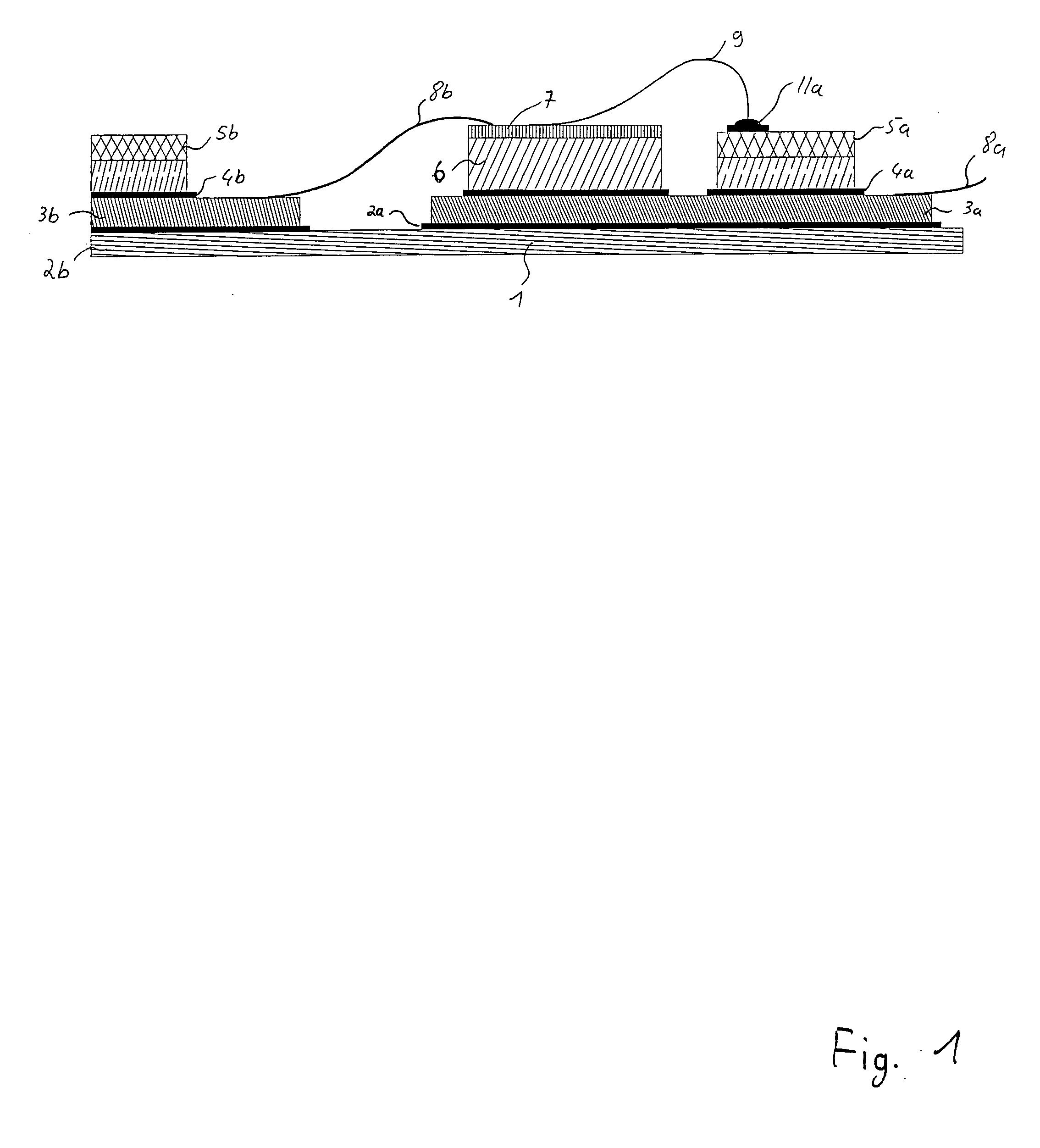
It is disadvantageous in this respect that a large number of individual parts is required, for which costs accrue in the supply and in the mounting and manufacturing logistics.
This large number of operating steps increases the cycle times and lowers the throughput of a manufacturing line for solar cell modules in concentrator photovoltaics.
The material expenditure is also very high and incurs high costs.
In particular, some steps for producing the solar module are particularly expensive, such as for example the soldering processes.
The material costs for the silver strips 8b for example are likewise very high.

Method used


Image

  • Solar Cell Module and Method For Its Production
  • Solar Cell Module and Method For Its Production
  • Solar Cell Module and Method For Its Production

Examples


Embodiment Construction

[0031]FIG. 2 shows a section of a solar module according to the present invention. The present invention concerns solar cell modules for concentrating solar systems. The sunlight is hereby focused with the help of an optics on a tiny focal spot in which then only one small solar cell is situated. The solar cell modules according to the invention now consist of a planar, two-dimensional array comprising corresponding concentrator optics which produce a two-dimensional array of focal spots. A solar cell is now disposed in each focal spot. This has the advantage that highly efficient solar cells can be used in the concentrating solar technology. Hence an array of Fresnel lenses is used for example in so-called Flatcon™ technology, said lenses concentrating the sunlight by a factor of 300 to 1,000 and focusing on a small focal spot. In each focal spot of each individual Fresnel lens there is then situated a 1 to 10 mm2 small solar cell. Hence overall expensive semiconductor surface of h...


PUM


Abstract

A solar cell module and a method for the production thereof, are used in particular in the field of concentrating solar technology. The solar cell module has a large number of two-dimensionally disposed solar cells. These solar cells are applied on a substrate which is coated with a metal layer on the surface orientated towards the solar cells. The metal layer is thereby structured in such a manner that it is subdivided into individual two-dimensional portions which are assigned respectively to one solar cell. The metal layer in each of the portions has two regions which are electrically insulated from each other, the first region extending under the assigned solar cell and contacting the latter in an electrically conductive manner. The second region is likewise connected to the other electrical contact of the solar cell. In order to produce a parallel and series circuit of the individual solar cells, the individual portions of the metal layer are now connected to each other in a suitable manner by means of connecting portions which, for their part, are part of the metal layer.

Description

BACKGROUND OF THE INVENTION[0001]The present invention relates to a solar cell module and to a method for the production thereof. Solar cell modules of this type are used in particular in the field of concentrating solar technology.[0002]In photovoltaics, a plurality of solar cells are combined together to form larger modules. Within one module, a plurality of solar cells are wired up together, the module takes over further tasks in addition, such as e.g. protection of the generally very sensitive cells from weathering effects.[0003]A special field of photovoltaics is so-called “concentrator photovoltaics” in which sunlight is concentrated by an optical system (e.g. lens, mirror) and the concentrated light beam impinges—according to the type of plant—on a relatively small solar cell.[0004]For this purpose, the cell must be positioned exactly in the focus of the lens. Due to the small size of the cells, frequently special contacting methods (e.g. bonding) are necessary in order to co...

Claims


Application Information

Patent Timeline
Patent Type & Authority Applications(United States)
IPC IPC(8): H02N6/00B05D5/12
CPCH01L31/052Y02E10/50H01L31/0543H01L31/0504H01L31/0508H01L31/0475Y02E10/52H01L31/042
Inventor JAUS, JOACHIMBETT, ANDREASBOESCH, ARMINDIMROTH, FRANKLERCHENMUELLER, HANSJOERG
Owner FRAUNHOFER GESELLSCHAFT ZUR FOERDERUNG DER ANGEWANDTEN FORSCHUNG EV
Learn More