
Durable tool for molding of polymer composites

Active Publication Date: 2008-10-02
GM GLOBAL TECH OPERATIONS LLC
View PDF6 Cites 35 Cited by
  • Summary
  • Abstract
  • Description
  • Claims
  • Application Information

AI Technical Summary

Benefits of technology

[0008]It is found that Invar-36 type tooling may be made more durable for high volume production of carbon cloth (or other fiber structures) reinforced polymer matrix parts without adversely affecting its desirable thermal expansion properties in relation to the thermal expansion properties of the molded composite material. In other words, this invention retains the dimensional accuracy of the Invar-36 type mold material while providing a hard, wear resistant surface. Carbon fiber-containing composite parts with good dimensional accuracy may be repetitively made in large volume production using the improved tooling.
[0011]The use of the electroless nickel coated, nickel-iron tooling of this invention is applicable to the many various molding practices for the forming of carbon fiber composite parts. The hard surface provides abrasion resistance against the composite materials. The adherent coating and underlying substrate cooperate to retain good dimensional properties for the repetitive molding of substantially identical parts as required in the automotive and other industries.

Problems solved by technology

And the low production volumes permit the use of molding tool materials that do not provide hard surfaces for resisting wear from the abrasive composite materials.
The tooling material is considered to be too soft for production of a large number of composite parts.
The hardness of Invar-36 (80 HRB) is significantly lower than that of the P20 tool steel (50 HRC), suggesting that Invar tooling will not be sufficiently wear-durable by automotive standards even for low volume production.

Method used


Image

  • Durable tool for molding of polymer composites
  • Durable tool for molding of polymer composites
  • Durable tool for molding of polymer composites

Examples


example 1

Autoclave Cured, Hand Lay-Up, Carbon Fiber Composite Laminate Molding

[0031]This process is currently being used to make automotive vehicle body panels in very low volume. Substantially unidirectional carbon cloths sheets (about 0.2 mm thick) impregnated with a liquid epoxy resin precursor composition (40% by weight of the composite) are cut into predetermined patterns. The sheets are laid-up as plies on the cavity surface of a single Invar-36 tool. For example, six plies are laid-up to a total thickness of about 1.2 mm, with successive layers of carbon fibers oriented in different directions to obtain suitably isotropic properties in a molded panel. The laid-up sheet body is covered with a plastic film and sealed around its perimeter for removal of air by vacuum. The entire assembly is loaded into an autoclave for compression against the tool surface and heating to cure the epoxy resin matrix. The tool and cured composite material are removed from the autoclave and cooled, and the f...

example 2

Liquid Molding Process—Resin Transfer Molding (RTM) and Reaction Injection Molding (RIM)

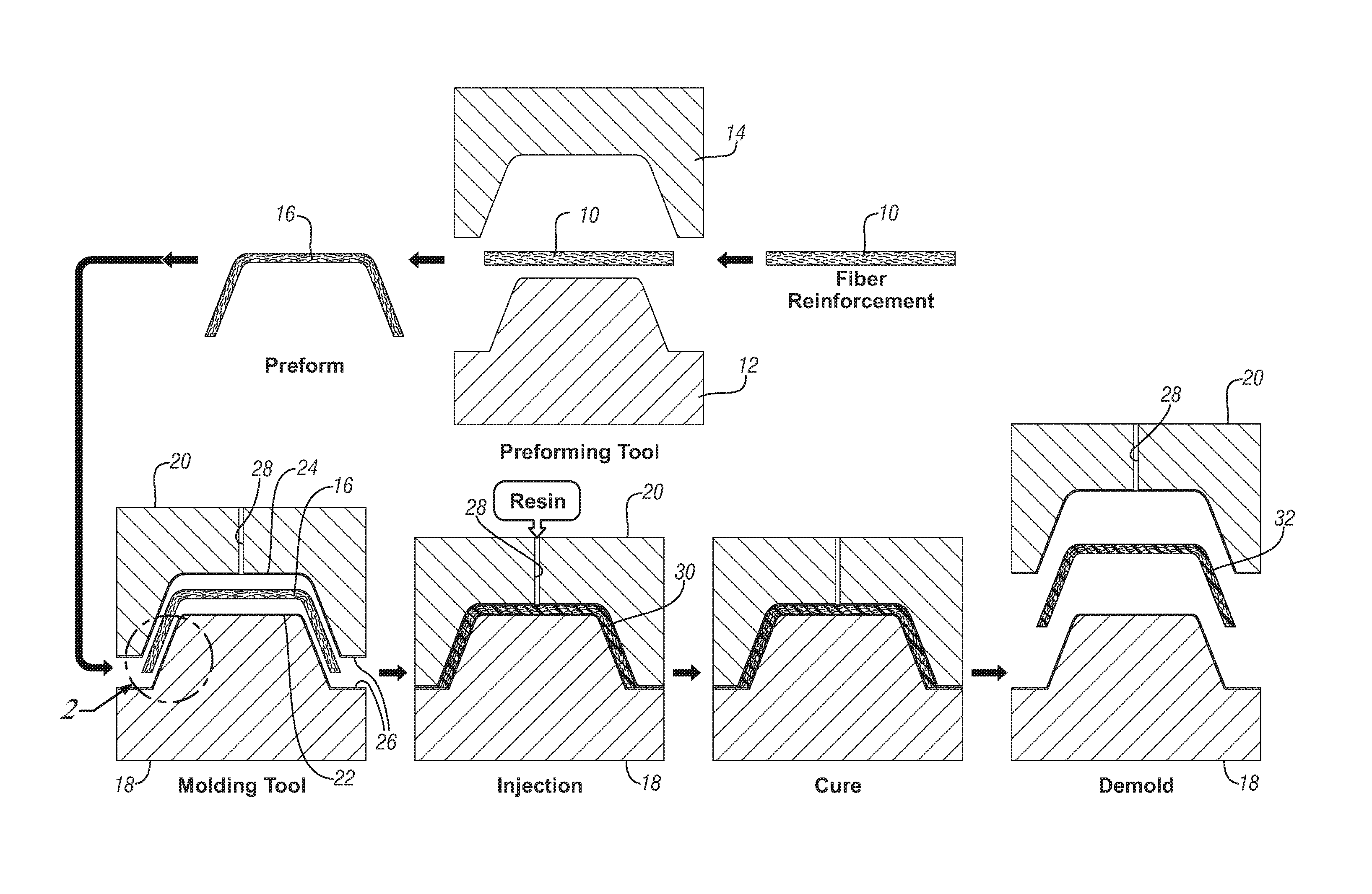
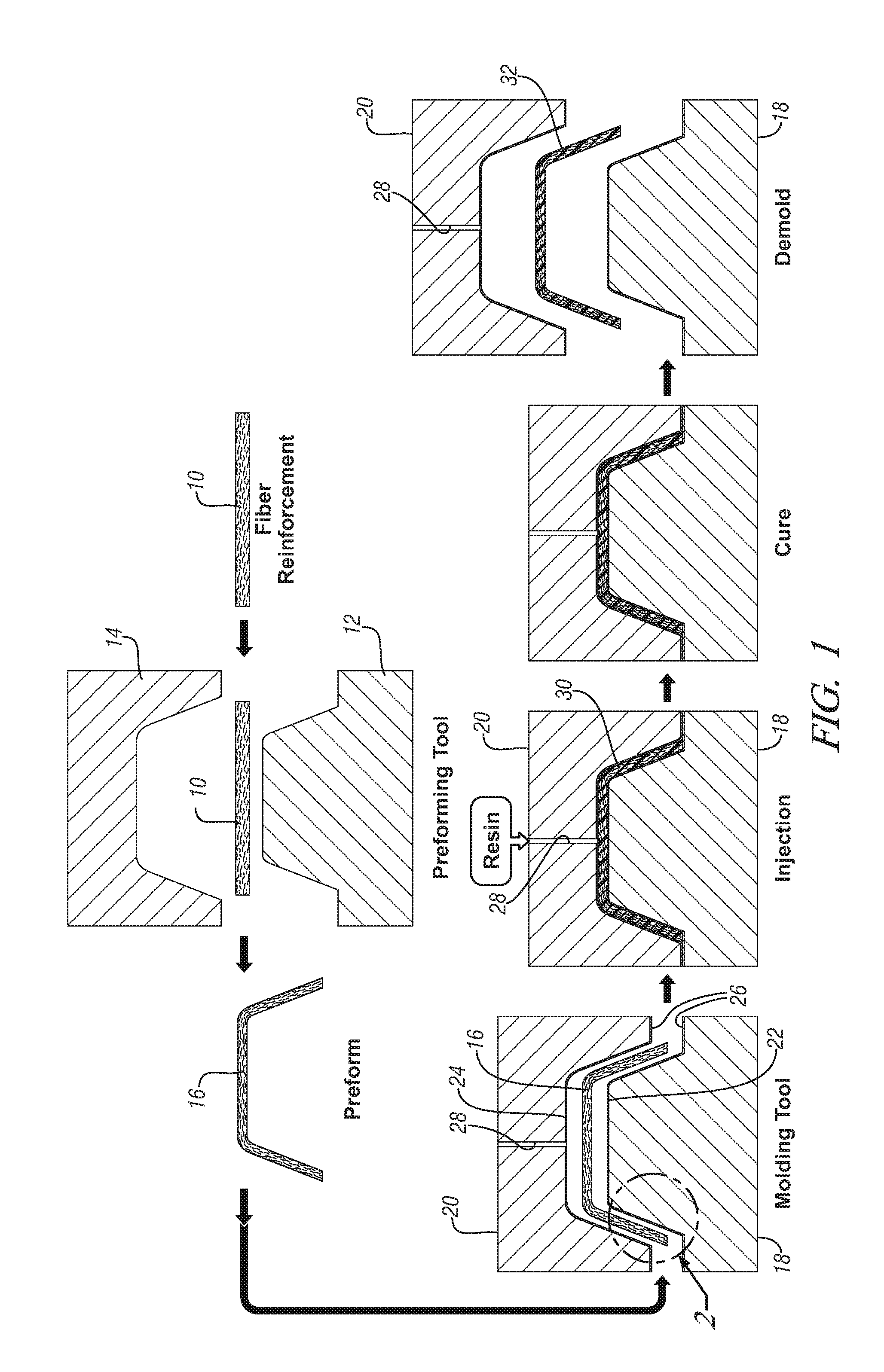
[0034]Liquid molding is capable of producing carbon fiber composites up to 100,000 parts per year per tool, depending on the resin chemistry used in the process. There are various forms of liquid molding process and the most widely used are RTM and RIM. The process is illustrated with reference to the schematic flow diagram of FIG. 1.

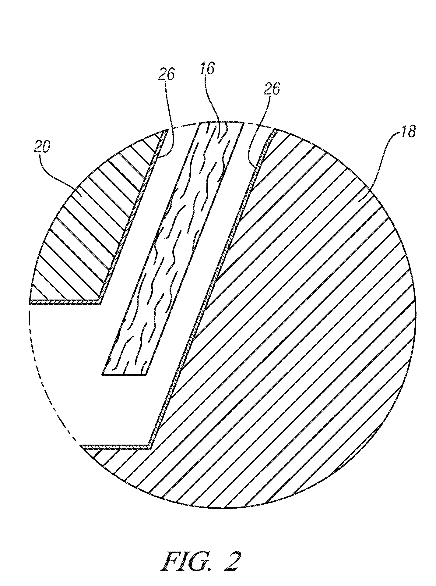
[0035]Referring to FIG. 1, a sheet-like or slab-like multi-layer body 10 (also identified as Fiber Reinforcement in FIG. 1) of carbon fiber cloth is placed between opposing and complementary preforming tools consisting of a lower (as illustrated in the drawing figure) male preforming tool 12 and an upper female preforming tool 14. The set of tools 12, 14 is also identified as Preforming Tool in the drawing figure. At the stage of illustration in FIG. 1, the tools 12 and 14 are vertically separated in their open position and the body 10 of carbon fiber cloth may be la...

example 3

Compression Molding

[0041]Compression molding is the most traditional process to produce both thermosetting and thermoplastic composite parts. Ni plated Invar tools can be used to mold carbon fiber composite parts for certain applications such as automotive inner parts. The materials suitable for this type of molding are carbon fiber epoxy prepregs (same as the materials used for autoclave molding), carbon fiber sheet molding compound, SMC (chopped carbon fibers in vinyl ester resin, for example), and various carbon fiber containing thermoplastic polymers such as polypropylene, polyamide, etc. The layers or bodies of prepreg material or SMC are loaded into the cavity of the opened, opposing complementary molding tools. The tools are closed to compress the uncured resin impregnated carbon fiber body in the cavity formed between them. Again, the tools are heated to cure the matrix resin material and then opened for removal of the hot molded part. For thermoplastic molding, the tools ar...


PUM

PropertyMeasurementUnit
Fractionaaaaaaaaaa
Fractionaaaaaaaaaa
Thicknessaaaaaaaaaa

Abstract

Mold tooling formed of suitable iron-nickel alloys and provided with a hard electroless nickel coating on the mold cavity surface are useful for high volume production of carbon fiber reinforced, polymer matrix, composites. The iron and nickel alloy provides thermal expansion properties for the molding of dimensionally accurate parts. The nickel alloy coating provides a durable surface, without adversely affecting the expansion properties of the mold, and remains adherent to the base metal during the repeated thermal cycling encountered in high volume production of substantially identical molded carbon composite parts.

Description

TECHNICAL FIELD[0001]This invention pertains to the molding of a succession of many like carbon fiber reinforced polymer parts such as in the production of light weight automotive vehicle body panels. More specifically, this invention pertains to the preparation and use of durable tooling for such repetitive molding operations on abrasive materials.BACKGROUND OF THE INVENTION[0002]Carbon fiber composite parts comprise carbon fiber cloth impregnated with a matrix polymer such as a suitable epoxy resin composition. While epoxy resins are commonly used matrix polymers, other polymers such as polyester resins, vinyl ester resins, polypropylene resins, or polyamide resins are also suitable. In low volume production of a given part, a thermosetting composite article is usually produced by layering sheets of carbon fiber cloth onto a mold cavity surface that defines the shape of the desired product. The alignment and weave of the carbon fibers in the cloth may be important in the mechanica...

Claims


Application Information

Patent Timeline
IPC IPC(8): B28B13/00B29C70/28
CPCB29C33/38B29C33/56B29C70/345B29C70/46B29C70/48B29C70/54B29K2023/12B29K2031/00B29K2063/00B29K2067/00B29K2077/00B29K2707/04B29L2031/3005B29L2031/3055
Inventor WANG, CHEN-SHIHWANG, YAR-MING
Owner GM GLOBAL TECH OPERATIONS LLC
Learn More