
Methods of macromolecular analysis using nanochannel arrays

a nanochannel array and macromolecular technology, applied in the field of nanoscale devices, can solve the problems of dna damage in the form of gene mutation, affecting the general analysis of large genomic regions, and taking on average 7-10 years and 800 million dollars to bring a new drug,

Active Publication Date: 2008-10-02
BIONANO GENOMICS
View PDF57 Cites 120 Cited by
  • Summary
  • Abstract
  • Description
  • Claims
  • Application Information

AI Technical Summary

Benefits of technology

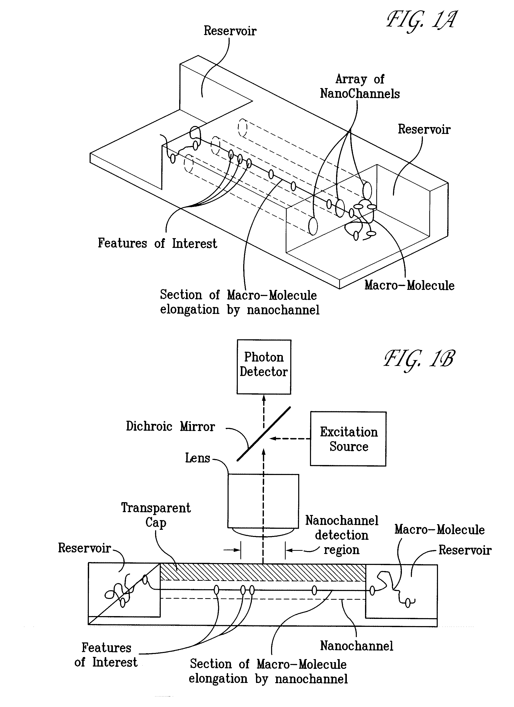
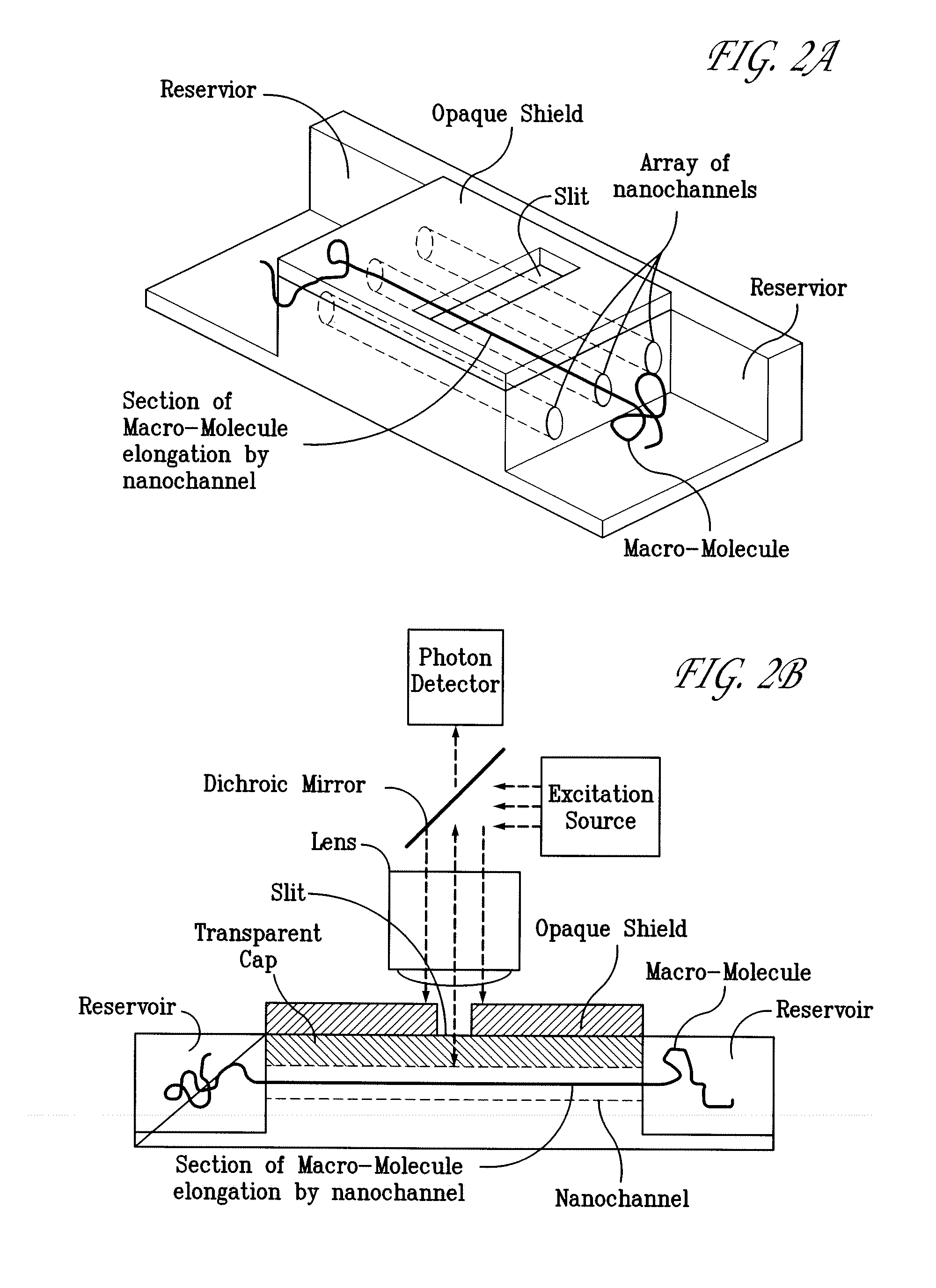
[0029]The present invention also teaches methods of of fabricating a macromolecular analysis device, comprising defining one or more nanochannels on a surface by disposition of two or more borders, one or more of the borders being capable of constraining a macromolecule, and one or more of the nanochannels having a width of less than about 1000 nm.

Problems solved by technology

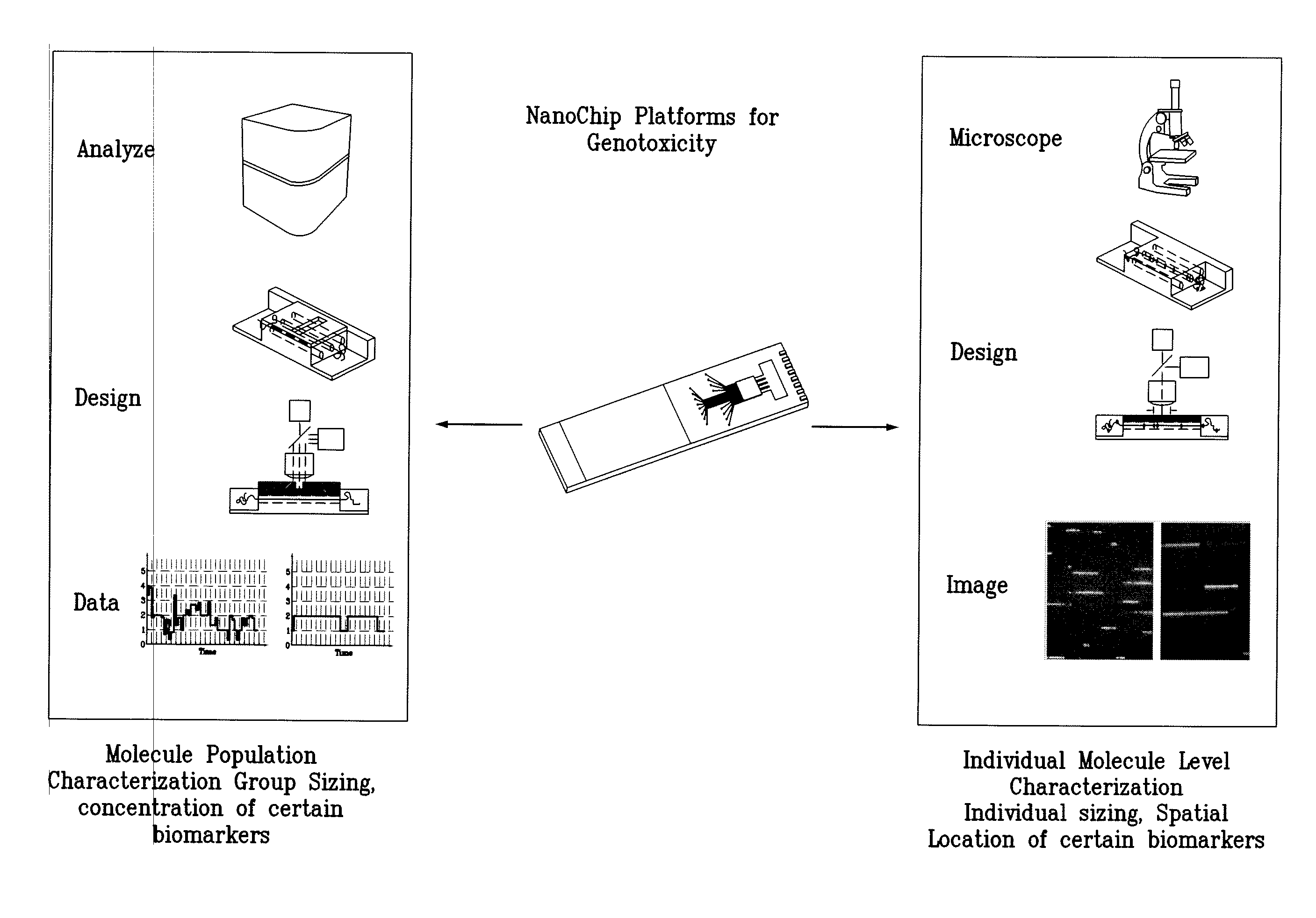
Most genome or epigenome analysis technologies remain too tedious or expensive for general analysis of large genomic regions or for a large population.
Additionally, it takes on average 7-10 years and 800 million dollars to bring a new drug to market.
Drug compound toxicity can result in damages to DNA in the form of gene mutations, large scale chromosomal alterations, recombination and numerical chromosomal changes.
A drug can be toxic at different levels, but drug-induced mutagenesis of DNA, such as germ line mutations, underlies many long term adverse effects.
Despite the guidelines set by government regulatory authorities, there are cases of drug toxicity, including the recent issues concerning the COX-2 group of pain killers.
The toxicity failure rate in the developmental pipeline has remained unimproved over the years contributing to the ever increasing costs of the process.
During compound screening, preclinical testing involves both in vitro and animal assays that assess efficacy and potential side effects to predict how the agent will affect humans, but the cost and speed associated with these genotoxicity tests have prohibited the wider use and earlier testing to improve the screening efficiency.
But even the improved version of the Ames test takes requires 2-4 days to process and costs $4,000 to $5,000 per test to complete.
In the area of DNA damage assessment, decades-old conventional cytogenetic analysis (from karytotyping, G-banding to various forms of FISH) techniques often rely on a spread of metaphase DNA, their resolution is limited to the megabase scale.
Interface or fiber-FISH methods attempt to improve the resolution by using relaxed or partially stretched DNA but they are still hard to implement and present challenges when trying to extract quantitative spatial information.
Powerful as these techniques are, they suffer from poor control of the processes since they lack consistency and repeatability, hence are ultimately subject to the skill of the technician making them difficult to scale up for faster and cheaper genotoxicity tests.
Unfortunately, the methods of the target DNA elongation are not inherently well controlled, the molecule elongation state is often transient, non-uniform and inconsistent, deeming complicated analytical process.
Such variability limits the application of this group of single molecule analysis approach for large scale screening of chromosomal DNA structural damages in genotoxicity tests.
In the case of large polymer fragments, the separation time could take hours or even days.
Though this technique offers an assessment of the degree of damage, it is difficult to standardize and the data is subject to interpretation.
Also, the fragments of chromosomal DNA remained entangled and cannot be distinguished from each other thus obscuring valuable information regarding the location of breaks or the size of individual fragments.
Other array based approaches such as Comparative Genomic Hybridization (CGH) have progressed in overcoming some aspects of resolution issues in detecting unbalanced genomic structural changes (amplification, deletion not translocation or inversion) however are limited to the issues inherit to comparative hybridization.
A drawback of this approach is that gross genetic changes, usually at much larger scale, can often be obscured because each individual fragment is removed from the context of the entire genome.
Accordingly, such techniques lack the ability to provide information regarding the whole of a genome, as opposed to a discrete region within the genome.
Unfortunately, this method of stretching is not inherently well controlled, and DNA samples on different microslides can never be “combed” identically, and there is no way to predict the degree, uniformity of stretching or placement of the molecules on a surface.
Such variability accordingly limits the application of the combing approach to large scale screening of patients.
Other attempts to standardize the linearization of individual DNA molecules using fluidic biochip platforms proved relatively inefficient in effecting the desired linearization.
The resolution of such techniques, furthermore, is poor, because the elongation of the DNA is often transient, non-uniform and inconsistent, and images used in analysis must be captured while the DNA moves at a high enough velocity to sustain its elongated state.
In addition, because these designs are based around a single channel through which flow molecules past an optical detector, their throughput is severely limited.

Method used


Image

  • Methods of macromolecular analysis using nanochannel arrays
  • Methods of macromolecular analysis using nanochannel arrays
  • Methods of macromolecular analysis using nanochannel arrays

Examples


example 1

[0154]A silicon substrate having a plurality of parallel linear channels that had an 100 nm trench width and a 100 nm trench height was provided. These channel openings were sputtered at a gas pressure of 5 mTorr according to the general procedures given above. The sputter deposition time was 10-25 minutes to provide a nanochannel array that can range from not completely sealed to completely sealed. Silicon dioxide was deposited by an e-beam (thermo) evaporator (Temescal BJD-1800) onto the substrate. The substrate was placed at various angles incident to the depositing beam from the silicon dioxide source target; the deposition rate can be set to about 3 nm / minute and 150 nm of sealing material was deposited in about 50 minutes. The angle of the incident depositing beam of sealing material could be varied to reduce the channel width and height to less than 150 nm and 150 nm, respectively, and to substantially sealed by providing shallow tangential deposition angles.

example 2

[0155]In this example, a nanochannel array was contacted with a surface-modifying agent. A nanochannel array made according to Example 1 can be submerged in a surface-modifying agents solutions containing polyethelyene glycol inside a vaccum chamber to facilitate wetting and treatment of the channels and degas the air bubbles that might be trapped inside the nanochannels.

example 3

[0156]This example describes how to provide a sample reservoir with a nanochannel array to provide a nanofluidic chip. A nanochannel array having 100 nm wide, 100 nm deep nanochannels was made according to general procedures of Example 1. The nanochannel array was spin-coated with a photoresist and imaged with a photomask to provide regions on opposite ends of the channel array. The exposed areas were etched using reactive ion etching to expose the nanochannel ends and to provide a micron-deep reservoir about a millimeter wide on the opposite ends of the channels at the edge of the substrate.


PUM

PropertyMeasurementUnit
lengthaaaaaaaaaa
lengthaaaaaaaaaa
lengthaaaaaaaaaa

Abstract

Methods of analyzing features such as the physical size of macromolecules or biomarkers along large genomic DNA molecules were disclosed as well as the devices for carrying out such high throughput analysis in a massively parallel fashion. Methods of fabricating such devices are also disclosed.

Description

CROSS-REFERENCE TO RELATED APPLICATIONS[0001]The present application claims the benefit of U.S. application Ser. No. 60 / 908,582, and U.S. application Ser. No. 60 / 908,584, filed on Mar. 28, 2007, the entireties of which are incorporated herein by reference.STATEMENT OF GOVERNMENT RIGHTS[0002]This invention was made with U.S. Government support. The Government may have certain rights in the invention under National Institutes of Health grant 1R43HG004199-01.COLOR DRAWINGS[0003]The file of this patent contains at least one drawing / photograph executed in color. Copies of this patent with color drawing(s) / photograph(s) will be provided by the Office upon request and payment of the necessary fee.FIELD OF THE INVENTION[0004]The field of the invention includes nanoscale devices, and methods of making and using such devices, for macromolecular analysis. The field of the invention also includes polynucleic acid sizing and structural analysis.BACKGROUND OF THE INVENTION[0005]Various scientific...

Claims


Application Information

Patent Timeline
Patent Type & Authority Applications(United States)
IPC IPC(8): C40B30/04C40B60/12C40B30/10C40B30/06
CPCB01L3/502761G01N33/582B01L2200/0668B01L2200/12B01L2300/041B01L2300/0654B01L2300/0816B01L2300/0864B01L2300/0887B01L2300/089B01L2300/161B01L2400/0406B01L2400/0415B01L2400/0487B01L2400/086G01N21/6428G01N21/645C12Q2563/107B01L2200/0663G01N33/52B01L3/50273B01L2300/0627B01L2300/0861B01L2300/0896C12Q1/6874C12Q1/6876C12Q2600/172
Inventor CAO, HANDESHPANDE, PARIKSHIT A.AUSTIN, MICHAEL D.BOYCE-JACINO, MICHAEL
Owner BIONANO GENOMICS
Learn More