Solid electrolytic capacitor and method of manufacturing the same

a technology electrolytic capacitors, which is applied in the direction of electrolytic capacitors, liquid electrolytic capacitors, coatings, etc., can solve the problems of esr liable to increase with the lapse of time, esr of solid electrolytic capacitors tend to increase with time, etc., to suppress the penetration of external oxygen or water, prevent the increase of interfacial resistance, and suppress the effect of carbon layer peeling

Active Publication Date: 2008-10-09
PANASONIC CORP
View PDF6 Cites 4 Cited by
  • Summary
  • Abstract
  • Description
  • Claims
  • Application Information

AI Technical Summary

Benefits of technology

[0011]In the solid electrolytic capacitor of the present invention, the carbon layer contains the first additive or the second additive, and therefore, the adhesion of the carbon layer to the solid electrolyte layer can be maintained even in a high temperature environment. Accordingly, peeling of the carbon layer can be suppressed. As a result, it is possible to prevent

Problems solved by technology

However, in the case of the conventional solid electrolytic capacitor, when exposed in a high temperature environment, ESR t

Method used


Image

  • Solid electrolytic capacitor and method of manufacturing the same
  • Solid electrolytic capacitor and method of manufacturing the same
  • Solid electrolytic capacitor and method of manufacturing the same

Examples


first exemplary embodiment

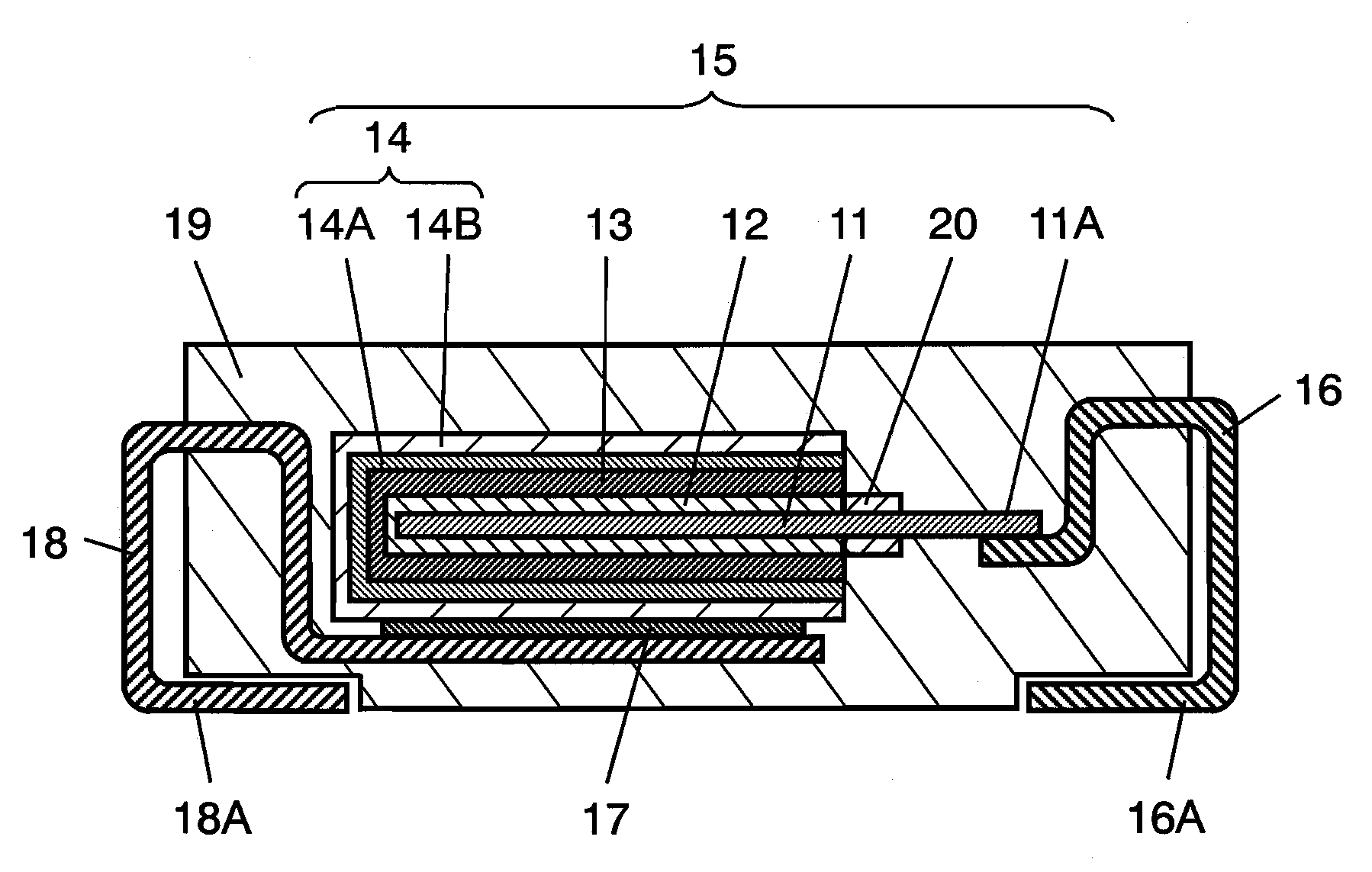
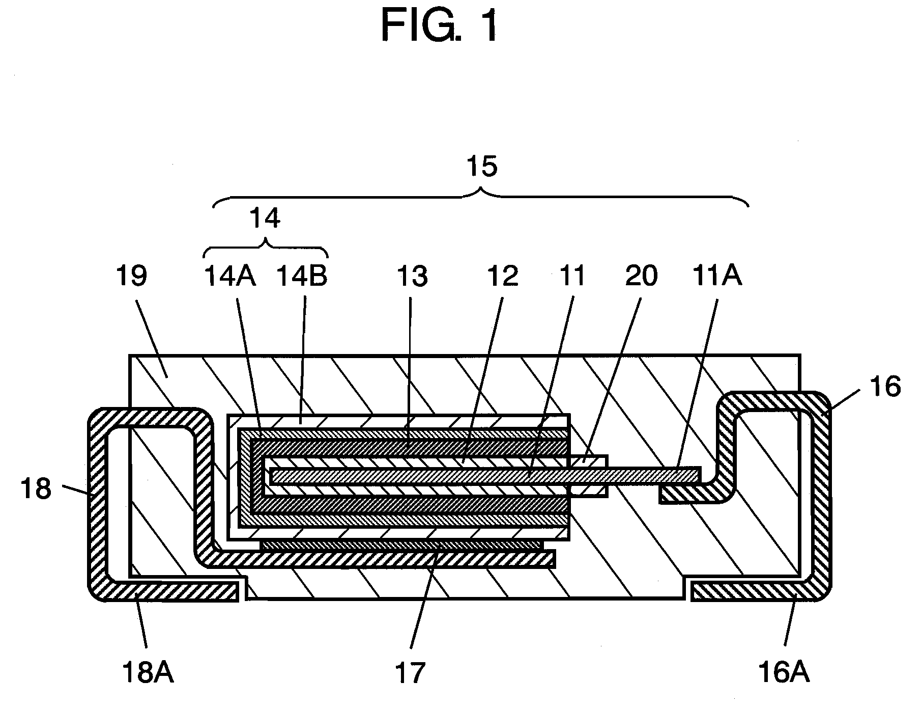
[0014]FIG. 1 is a sectional view showing the configuration of an aluminum electrolytic capacitor which is an example of solid electrolytic capacitor according to a first exemplary embodiment. The solid electrolytic capacitor includes capacitor element 15, anode terminal 16, cathode terminal 18, and exterior resin 19. Capacitor element 15 is formed of anode body 11, dielectric oxide layer 12, solid electrolyte layer 13, and cathode layer 14.

[0015]Anode body 11 is formed of a foil of a valve metal such as aluminum, and its surface is roughed by etching to enlarge the surface area. Also, the end portion thereof also serves as anode lead-out portion 11A. Anode lead-out portion 11A and anode body 11 are separated from each other by insulating resist material 20 disposed so as to come into tight contact with the surface of the foil. Dielectric oxide layer 12 is formed by chemical treatment of the surface of anode body 11.

[0016]Solid electrolyte layer 13 is formed on dielectric oxide layer...

second exemplary embodiment

[0072]In a solid electrolytic capacitor of the present exemplary embodiment, carbon layer 14A includes a second additive instead of the first additive in the first exemplary embodiment. The second additive is formed from at least one of those selected from the group consisting of a condensation product of an aromatic sulfonic acid with formaldehyde, a condensation product of an aromatic sulfonate with formaldehyde, polystyrene sulfonic acid, and polystyrene sulfonate. The other configuration is same as in the first exemplary embodiment described by using FIG. 1, and only the difference will be described in the following.

[0073]As specific examples of the second additive, the condensation product of aryl phenol sulfonic acid with formaldehyde (aryl phenosulfonic acid formaldehyde condensate), the condensation product of phenol sulfonic acid with formaldehyde (phenosulfonic acid formaldehyde condensate), the condensation product of anthraquinone sulfonic acid with formaldehyde, the con...


PUM


Abstract

A carbon layer is formed on a solid electrolyte layer of the solid electrolytic capacitor, and a conductor layer connected to a cathode terminal is further disposed thereon. The carbon layer contains carbon particles, and a first additive or a second additive. The first additive is formed from at least one of those selected from the group consisting of hydrated silica and silicate. The second additive is formed from at least one of those selected from the group consisting of a condensation product of an aromatic sulfonic acid with formaldehyde, a condensation product of an aromatic sulfonate with formaldehyde, polystyrene sulfonic acid, and polystyrene sulfonate.

Description

BACKGROUND OF THE INVENTION[0001]1. Field of the Invention[0002]The present invention relates to a solid electrolytic capacitor used for various electronic equipments, and a method of manufacturing the same.[0003]2. Background Art[0004]With the recent development of digital equipment, there is a strong demand for a capacitor being lower in equivalent series resistance (hereinafter referred as ESR) and excellent in high frequency characteristics. In order to meet such a demand, those using a solid electrolyte layer of manganese dioxide, polypyrrole, or polythiophene as electrolyte have been developed and commercialized.[0005]FIG. 2 is a sectional view of a conventional solid electrolytic capacitor. The solid electrolytic capacitor includes capacitor element 5, anode terminal 6, cathode terminal 8, and exterior resin 9. Capacitor element 5 is formed of anode body 1, dielectric oxide layer 2, solid electrolyte layer 3, and cathode layer 4.[0006]Anode body 1 is formed by sintering valve...

Claims


Application Information

Patent Timeline
IPC IPC(8): H01G9/15B05D1/00
CPCH01G9/0425H01G9/15H01G11/56Y02E60/13
Inventor MORI, HIROMIMATSUURA, HIROYUKISAITO, KAZUYOOZAWA, MASATO
Owner PANASONIC CORP
Why Eureka
Try Eureka