Optical Fiber Photocatalytic Reactor And Process For The Decomposition Of Nitrogen Oxide Using Said Reactor

a technology of nitrogen oxide and photocatalytic reactor, which is applied in the direction of physical/chemical process catalyst, separation process, organic chemistry, etc., can solve the problems of high conversion rate of methods, severe toxic photochemical smog, and low conversion rate of methods

Inactive Publication Date: 2008-12-18
NAT TAIWAN UNIV
View PDF2 Cites 21 Cited by
  • Summary
  • Abstract
  • Description
  • Claims
  • Application Information

AI Technical Summary

Problems solved by technology

These pollutant materials absorbed heat under the ultraviolet irradiation of the sun and thereby became chemically unstable, eventually resulting in severely toxic photochemical smog.
Such toxic smog irritates the eyes and respiratory tracts, as well as induces a variety of respiratory diseases, and thus, poses as a health hazard for humans.
However, this method has a low conversion rate.
Moreover, since the used photocatalyst must be washed with water for regeneration, it cannot be used continuously.
Consequently, this method is especially not suitable for decomposing boiler exhaust, which contains a higher content of nitrogen oxides.
However, these photocatalysts have a relatively large particle size, which promotes the recombination of electron and hole pairs, resulting in low photocatalytic reaction efficiency.
Such adhesive means is poor and tends to be weak due to the exfoliation of the photocatalysts from the optical fibers.
52, 213-223, 2004) and Hofstadler et al (Enviro. Sci. Technol., 1994, 28, 670-674), the TiO2 precursors were also selected for use, but were not subject to any thermal hydrolysis reaction treatment, resulting in an insufficient photocatalyst on the optical fibers after sintering.

Method used


Image

  • Optical Fiber Photocatalytic Reactor And Process For The Decomposition Of Nitrogen Oxide Using Said Reactor
  • Optical Fiber Photocatalytic Reactor And Process For The Decomposition Of Nitrogen Oxide Using Said Reactor
  • Optical Fiber Photocatalytic Reactor And Process For The Decomposition Of Nitrogen Oxide Using Said Reactor

Examples


example 1

The Preparation of a Photocatalyst

[0040]In this example, the following three types of photocatalyst were prepared: TiO2, α-Fe2O3, and ZnO. The TiO2 photocatalyst was prepared by via a thermal hydrolysis method, illustrated in the following steps. First, metal Pt was dissolved in advance in a 0.1 M aqueous nitric acid solution at a ratio of 1.0%, to which 17 mL titanium tetrabutoxide was slowly added. Upon completion of the addition of the titanium tetrabutoxide, the solution was heated to 80° C. and maintained at this temperature for 8 hours. The white colloid was dried in an oven at 80° C. for 24 hours. The resulting white solid material was calcined in a furnace at 500° C. Regarding the ZnO photocatalyst, commercially available powder was directly adopted. On the other hand, the α-Fe2O3 photocatalyst was synthesized via sol-gel method. In particular, isopropanol and iron nitrate (20 mmol) reacted for 20 minutes to form an α-Fe2O3 precursor solution, to which a thickener polyethyl...

example 2

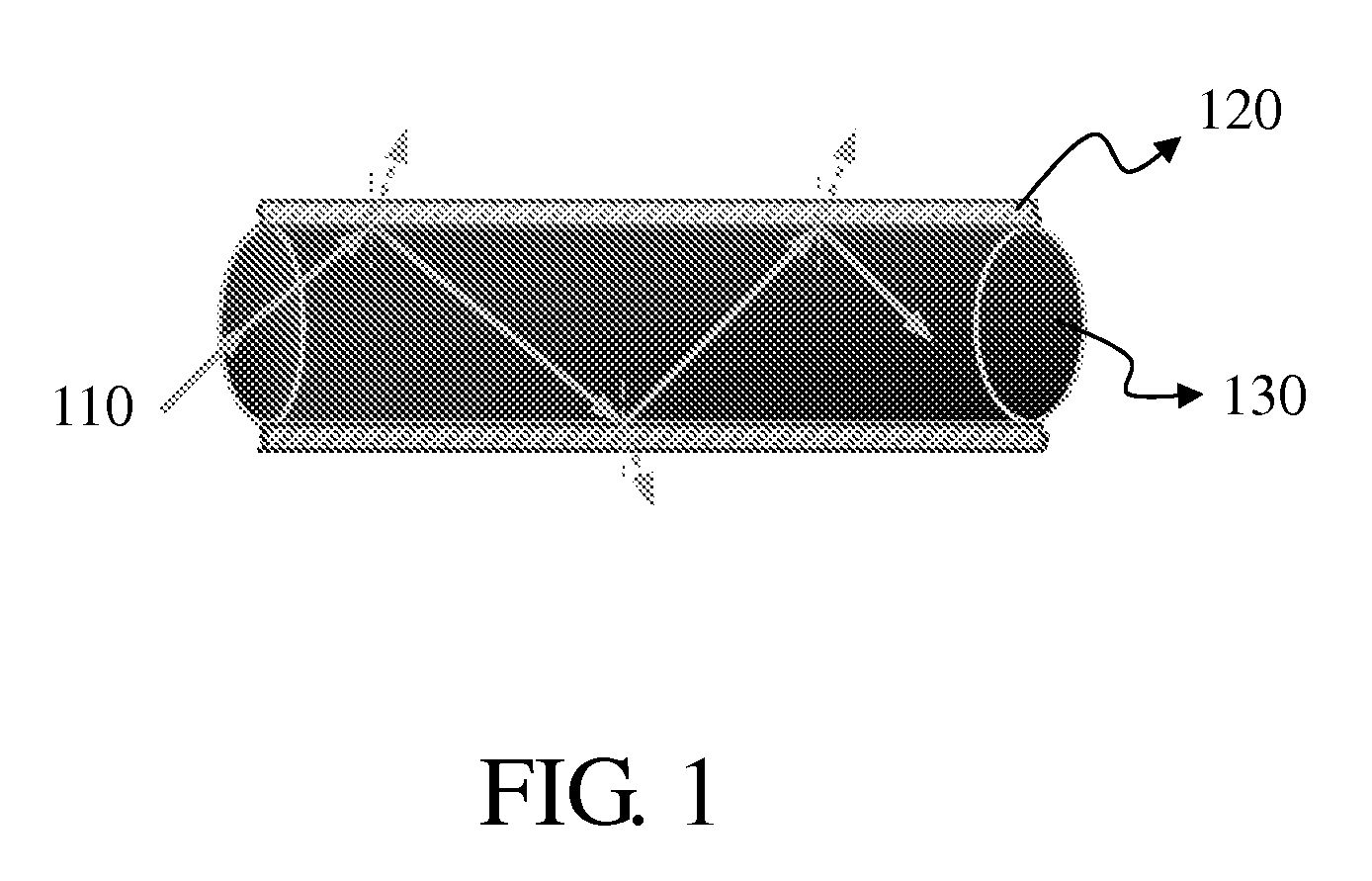
The Preparation of Optical Fibers Coated with a Photocatalyst

[0041]The preparation of the optical fibers coated with a photocatalyst was accomplished by adhering the white colloid obtained from Example 1 onto quartz optical fibers wherein the polymeric protection film had been removed from the surfaces. The method used was a dip coating process. Specifically, the optical fiber was thermally treated at 500° C. to remove the polymeric protection film on the surface, washed with an aqueous NaOH solution then alternately cleansed with water and dried. Next, the white colloid was placed in a container, and the optical fiber was dipped for 5 minutes. Thereafter, the optical fiber was pulled out with a speed of 3 cm / min, to obtain an optical fiber with a photocatalyst precursor adhered uniformly thereon. The resulting optical fiber was dried at 80° C. for 20 to 24 hours, and then was calcined at 500° C. to 700° C. in a furnace for 5 hours to become photocatalyst film on optical fiber.

example 3

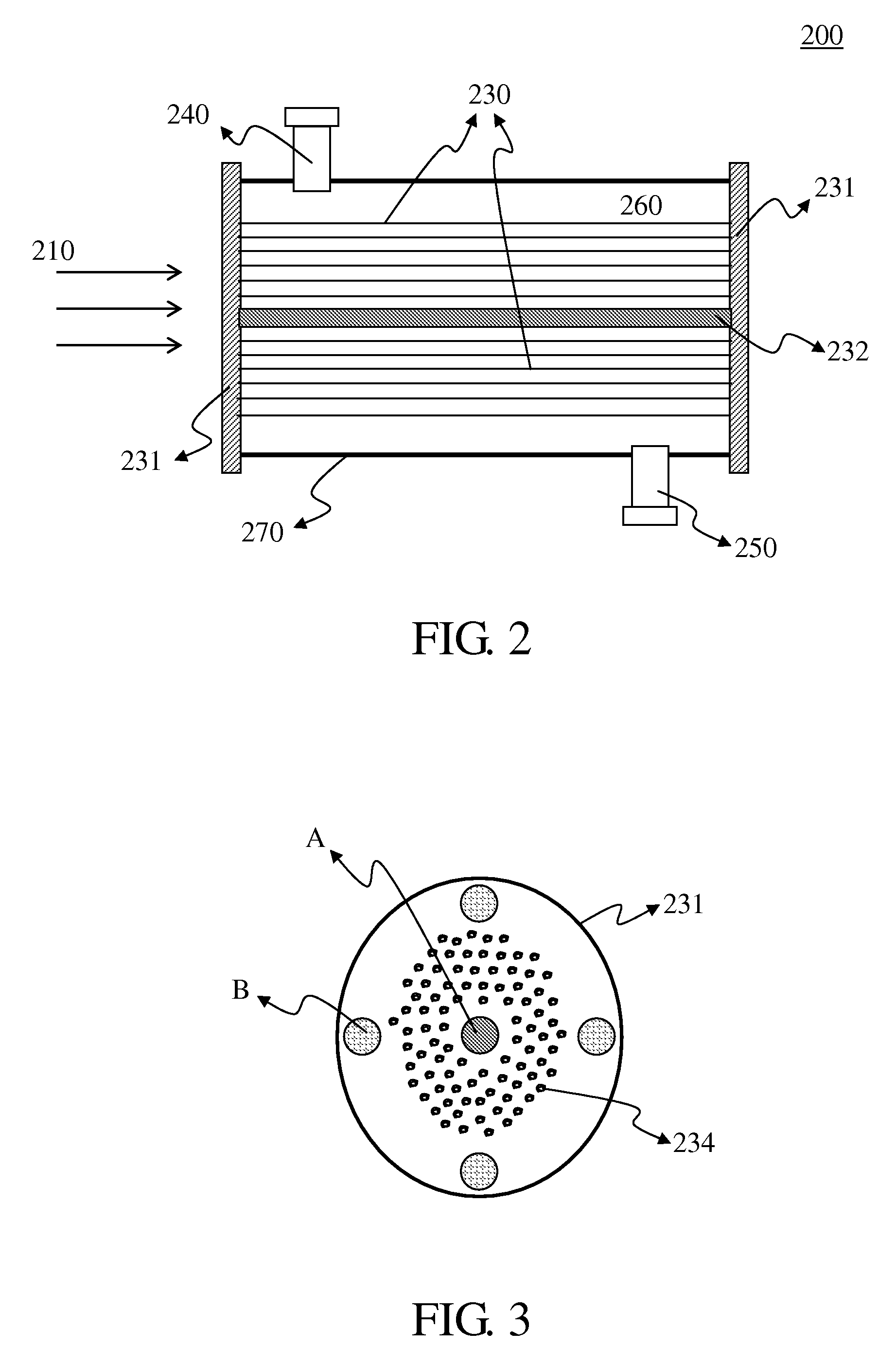
Continuous Photocatalytic Reaction (with CH4 as Reducing Agent)

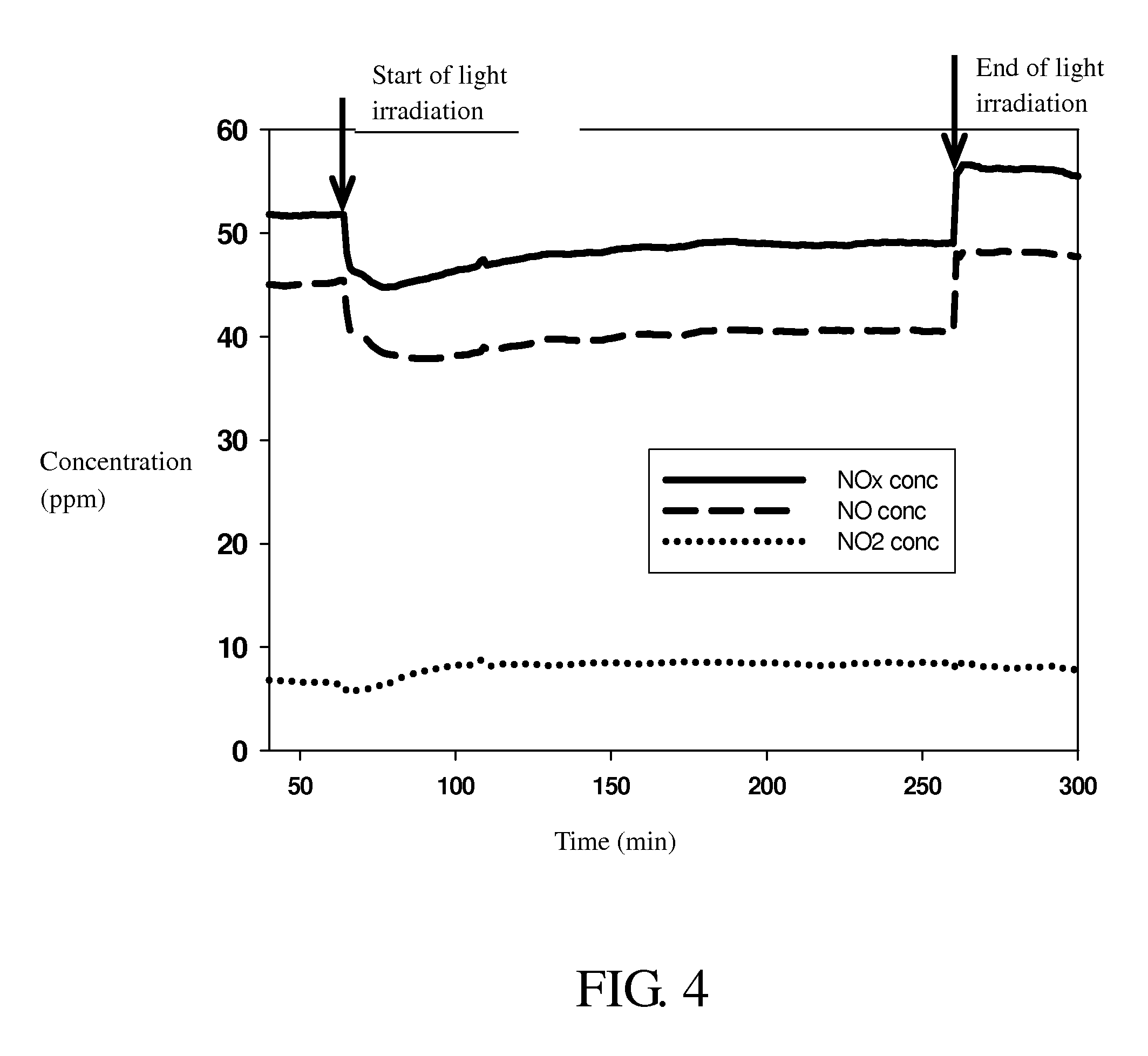
[0042]Hundreds of optical fibers with a TiO2 photocatalyst coating thereon obtained in Example 2 were fixed inside the reactor on the stainless steel shelves. A He stream was introduced through the reactor with a flow rate of 20 ml / min for one hour to purge the impurities therein. Subsequently, a CH4 stream with a 99% concentration level was introduced into the reactor under a flow rate of 60 ml / min for one hour, so that CH4 was adsorbed onto the surface of the photocatalyst. Finally, a 50 ppm nitrogen oxide stream was introduced into the reactor with a residence time of 60 minutes, followed by a resumed CH4 gas supply of a 99% concentration level with a residence time of 120 minutes. The light was transmitted into the reactor through optical fibers to activate the photocatalytic reaction using a metal halide lamp as the light source. Exhaust gas from the reactor outlet was delivered to a nitrogen oxide analyzer for the...


PUM

PropertyMeasurementUnit
temperatureaaaaaaaaaa

Abstract

An optical fiber photocatalytic reactor is provided. The reactor comprises a reaction zone and multiple fibers located in the reaction zone. The fiber comprises a photocatalyst that is coated onto its surface via a thermal hydrolysis method. The adhesion between the fiber and the photocatalyst thereon is strong, and thus, the delamination of the photocatalyst film on the fiber can be prevented. Moreover, the optical fiber photocatalytic reactor is useful for the decomposition of nitrogen oxide which is one of air's most harmful contaminants. The present invention exhibits a high conversion of nitrogen oxide.

Description

RELATED APPLICATION [0001]This application claims priority to Taiwan Patent Application No. 096121550, filed on 14 Jun. 2007, the disclosure of which is incorporated herein by reference in its entirety.BACKGROUND OF THE INVENTION [0002]1. Field of the Invention[0003]The present invention relates to an optical fiber photocatalytic reactor and its uses. Particularly, the present invention relates to the use of the reactor for the decomposition of nitrogen oxides.[0004]2. Descriptions of the Related Art[0005]The extent of air pollution is typically evaluated by the amount of fluorides, sulfur dioxide, nitrogen oxides (NOx), carbon monoxide and ozone in the air quality. For example, nitrogen oxides, comprising NO and NO2, are generally produced from the oxidization of N2 in the air or nitrides in various fuels during combustion. The main source of nitrogen oxides comes from the exhaust of automobiles, motor cycles and industrial boilers.[0006]During the 1960s in Los Angeles, Calif., U.S...

Claims


Application Information

Patent Timeline
Patent Type & Authority Applications(United States)
IPC IPC(8): B01D53/86B01J15/00B01J19/12
CPCB01D53/885B01D2255/802B01D2257/404
Inventor YU, YI HUIWU, JEFFREY CHI SHENGTSAI, DIN PINGHUANG, HUNG JICHU, TAI CHILAN, TAI WEI
Owner NAT TAIWAN UNIV
Why Eureka
Try Eureka