
Shower Plate and Method for Manufacturing the Same

a technology of shower plate and manufacturing method, which is applied in the field of shower plate, can solve the problems of mirror-finishing inner surface, significant increase in production cost, severe wear and tear, etc., and achieve the effect of preventing plasma backflow, reducing the flow resistance of a process gas to be blown out, and high degree of accuracy

Inactive Publication Date: 2009-01-01
TOKYO ELECTRON LTD +1
View PDF1 Cites 16 Cited by
  • Summary
  • Abstract
  • Description
  • Claims
  • Application Information

AI Technical Summary

Benefits of technology

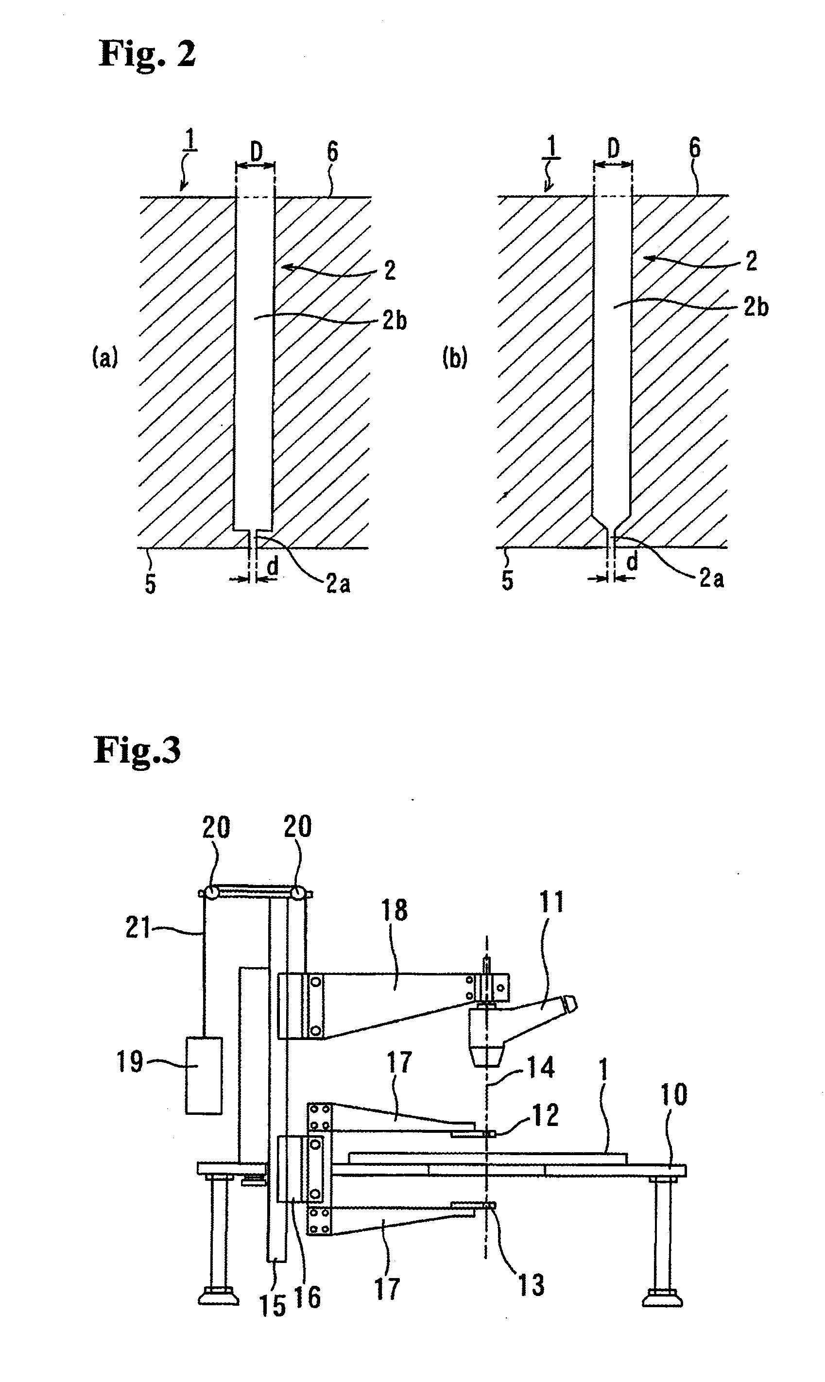
[0033]1. The outlet port of the blowing hole has a diametral dimension of from 0.1 mm to less than 0.3 mm, and the diametral dimension has a dimensional tolerance within ±0.002 mm. Thus, there is substantially no variation in flow rate of a process gas to be blown out from the large number of blowing holes.
[0034]2. The outlet port of the blowing hole has a small diametral dimension of from 0.1 mm to less than 0.3 mm. Thus, backflow of plasma can be prevented.
[0035]3. A film-forming operation or an etching operation can be performed for a large substrate (wafer) in a uniform or even manner which has not been able to be achieved by conventional shower plates, so as to manufacture high-quality semiconductors.
[0036]4. The blowing hole can have an inner surface with a surface roughness of 0.5 s or less. Thus, a flow resistance of a process gas to be blown out can be reduced.
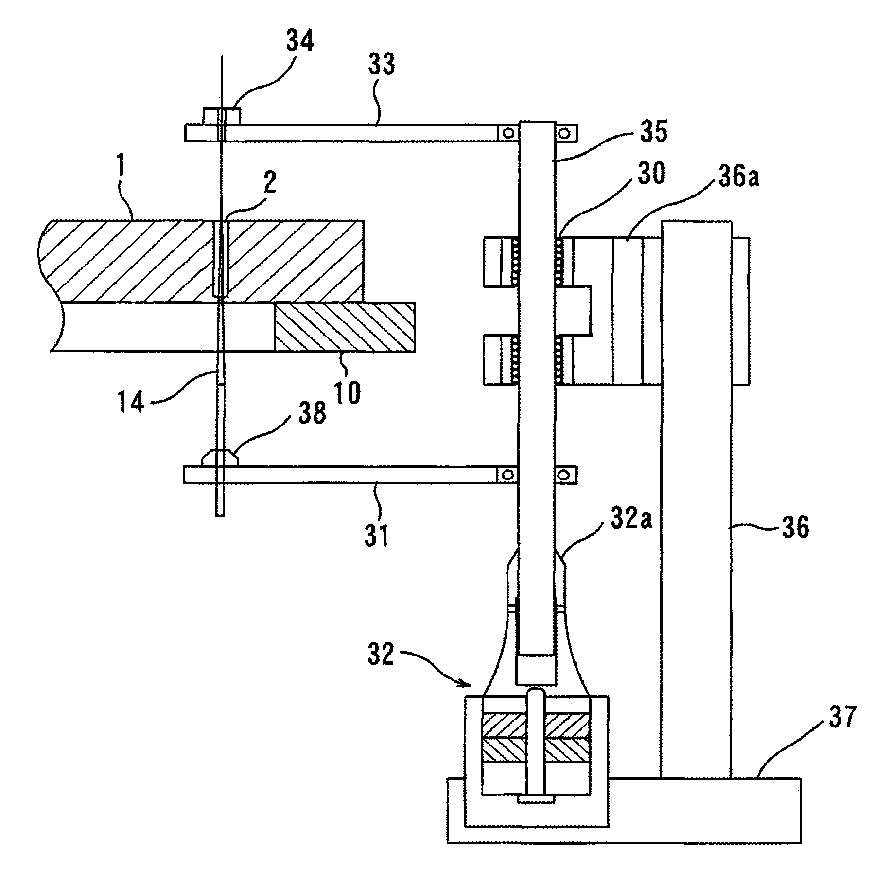
[0037]5. The blowing hole of the shower plate is lapped using the lapping wire having a taper-shaped end portion. This makes it possible to provide the blowing hole with high degree of accuracy, and stably manufacture shower plates having no variation in flow rate of a process gas to be blown out from the large number of blowing holes, i.e., having interchangeability.
[0038]6. The material of the shower plate has a high purity, and an excellent dielectric loss of 5×10⁻³ to 1×10⁻⁵. Thus, the shower plate can exhibit excellent transparency to microwave and low energy loss.

Problems solved by technology

These materials involve problems about difficulty in mirror-finishing inner surfaces of the small blowing holes, and severe wear and tear due to poor corrosion resistance to plasma to be generated from a fluorine or chlorine-based process gas in a reaction space.
This causes considerable increase in production costs.
Moreover, the shower plate has difficulty in reducing a frequency of outbreak of particles.
In addition, each of respective average grain sizes of alumina and YAG, a ratio between the average grain sizes, a fracture toughness value of the shower plate and a thermal shock resistance of the shower plate is limited to a specific range.
Thus, the drilling tool will be subject to severe wear or abrasion to cause an increase in tool costs, and a process time for machining the large number of fine-holes will be considerably extended.
Moreover, this ceramic material is a sintered material having high strength and hardness, and thereby it is extremely difficult to form an ultra-fine outlet port in view of a strength margin of a drilling tool.
Thus, due to an inevitable increase in tool diameter, the outlet port must be formed to have a diameter of 0.3 mm or more, which cases a problem about backflow of plasma as a consequent adverse effect.
Furthermore, it is extremely difficult to finish the plurality of fine-holes and outlet ports in a desired configuration and a desired dimensional tolerance with a high degree of accuracy.
Thus, unevenness in mixing of the resin material and variations in sintering degree and porosity will inevitably occur to cause difficulty in providing a shower plate with stable quality and interchangeability.
Moreover, in the shower plate formed of a porous body, grinding chips or fine particles generated during finish machining for outside dimensions will attach to the pores having a complicated configuration to cause a problem about outbreak of particles during an actual operation.

Method used


Image

  • Shower Plate and Method for Manufacturing the Same
  • Shower Plate and Method for Manufacturing the Same
  • Shower Plate and Method for Manufacturing the Same

Examples


example

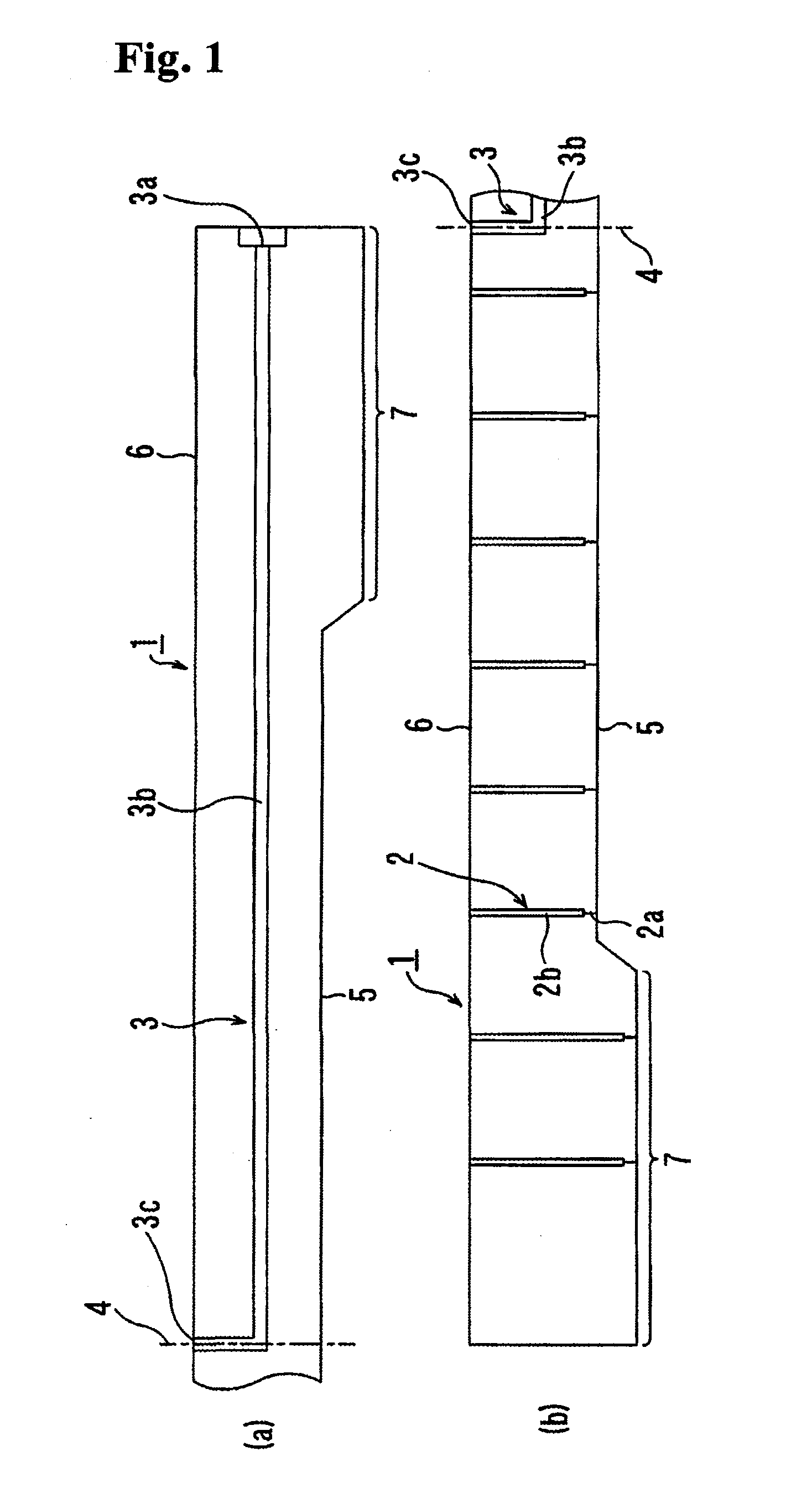
[0063]A specific example of the shower plate of the present invention and a manufacturing method therefor will be described with reference to FIG. 1.

[0064]A raw powder for sintering prepared by mixing an Y2O3 fine powder having a purity of 99.9% or more with an Al2O3 fine powder having a purity of 99.95% or more, in an amount of 0.1 to 5 mass %, was formed through a Cold Isostatic Press (CIP) to obtain a disc-shaped compact having a configuration determined in consideration of a sintering shrinkage value (i.e., a value of shrinkage due to sintering) and a machining value (i.e., a value to be machined). After machining one side region of a circumferential surface of the disc-shaped compact toward a center of the disc-shaped compact using a short drill having a diameter corresponding to that (Φ1 mm) of the gas inlet passage 3 of the finished shower plate, to form an inlet 3a, an elongated hole 3b was bored along an axis of the inlet 3a to extend up to the center of the disc-shaped com...


PUM

PropertyMeasurementUnit
diameteraaaaaaaaaa
diameteraaaaaaaaaa
diameteraaaaaaaaaa

Abstract

Disclosed is a shower plate which is formed with a large number of process-gas blowing holes having a simple structure, high machinability and high dimensional accuracy without the risk of unevenness in blowing of a process gas and outbreak of particles, while ensuring constant quality and interchangeability. Through a press forming process, a powder for a ceramic material with a low dielectric constant is formed into a disc-shaped compact having dimensions determined in consideration of a sintering shrinkage value and a machining value. A gas inlet passage 3 and a large number of blowing holes 2 for a compact stage are bored in the disc-shaped compact, and then the disc-shaped compact is sintered. Subsequently, the gas inlet passage 3 and a main hole portion 2b in each of the blowing holes are subjected to grinding to have a surface roughness of Is or less. Further, a lapping wire having a taper-shaped end is inserted into an outlet port 2a of the blowing hole 2, and reciprocatingly moved while being slidingly displaced in such a manner that a portion of the lapping wire located in the outlet port 2a is gradually increased in wire diameter, so that the outlet port 2a is lapped to have a diameter of from 0.1 mm to less than 0.3 mm, a dimensional accuracy within ±0.002 mm, and a surface roughness of 1 s or less.

Description

TECHNICAL FIELD[0001]The present invention relates to a shower plate which is used for supplying a process gas uniformly onto a large substrate (wafer) in a semiconductor manufacturing apparatus, and a method of manufacturing the shower plate.BACKGROUND ART[0002]Heretofore, in a semiconductor manufacturing process, there have been employed semiconductor manufacturing apparatus such as a CVD apparatus for film-formation and a dry etching apparatus in which a process gas is supplied onto a surface of a wafer.[0003]Such semiconductor manufacturing apparatus are adapted to apply a high-frequency voltage between a wafer and a shower plate from which a process gas is blown out, so as to energize the process gas into a plasma state to form a thin film on a surface of the wafer or etch the wafer surface.[0004]In view of ensuring machinability required for forming a large number of small blowing holes, the shower plate has been formed using a plate of aluminum, silicon or the like. These mat...

Claims


Application Information

Patent Timeline
Patent Type & Authority Applications(United States)
IPC IPC(8): H01L21/306H01L21/30C04B35/64B23P13/00
CPCB24B1/04B24B5/485C23C16/45565C04B35/111C04B35/6455Y10T29/49996C04B2235/3225C04B2235/3229C04B2235/77C04B2235/945C04B2235/3206H01J37/3244H01L21/67069
Inventor OKESAKU, MASAHIROOHMI
Owner TOKYO ELECTRON LTD
Learn More