Hydrocarbon getter for lithographic exposure tools

a lithographic exposure and hydrocarbon technology, applied in the direction of printers, instruments, therapy, etc., can solve the problems of increasing manufacturing costs, increasing the difficulty of achieving high dimensional accuracy in an efficient manner with high manufacturing throughput, and euv lithography exposure tools, which have been problematic, so as to reduce the carbon deposition on optical elements, reduce the effect of carbon deposition, and avoid adverse oxidation and adverse carbon deposition

Active Publication Date: 2009-01-01
ADVANCED MICRO DEVICES INC
View PDF7 Cites 3 Cited by
  • Summary
  • Abstract
  • Description
  • Claims
  • Application Information

AI Technical Summary

Benefits of technology

[0008]An advantage of the present invention is a lithographic exposure device with reduced carbon deposition on optical elements during use.
[0009]Another advantage of the present invention is an EUV lithography exposure tool capable of maintaining hydrocarbon levels to avoid adverse oxidation of and adverse carbon deposition on reflective optical elements.
[0010]A further advantage of the present invention is a method of reducing carbon deposition on the reflective optical elements of an EUV device.
[0011]Another advantage of the present invention is a method of controlling the amount of hydrocarbons in an EUV lithography exposure device to a level sufficie

Problems solved by technology

The dimensions of semiconductor device features relentlessly plunge into the deep sub-micron range challenging conventional fabrication capabilities.
As critical dimensions shrink, it becomes increasingly more difficult to achieve high dimensional accuracy in an efficient manner with high manufacturing throughput.
In addition to the limitations of conventional lithography, as dimensions shrink and memory capacity increases, manufacturing costs increase, thereby requiring advances in processing aimed at the efficient use of facilities and high manufacturing throughput.
Such EUV lithography exposure tools, however, have been problematic.
A major source of concern is the contamination of the reflective optical elements during operation due to residual gases from the vacuum atmosphere.
The reflectivity and the lifetime of these reflective optical elements are especially impa

Method used


Image

  • Hydrocarbon getter for lithographic exposure tools
  • Hydrocarbon getter for lithographic exposure tools
  • Hydrocarbon getter for lithographic exposure tools

Examples


Embodiment Construction

[0021]The present invention addresses and solves problems attendant upon the use of lithographic exposure tools, such as lithographic exposure tools that operate under a very short wavelength, e.g., soft X-ray and EUV wavelength range radiation, by minimizing and controlling carbon deposition on and preventing oxidation of reflective optical elements, thereby reducing downtime and increasing manufacturing throughput.

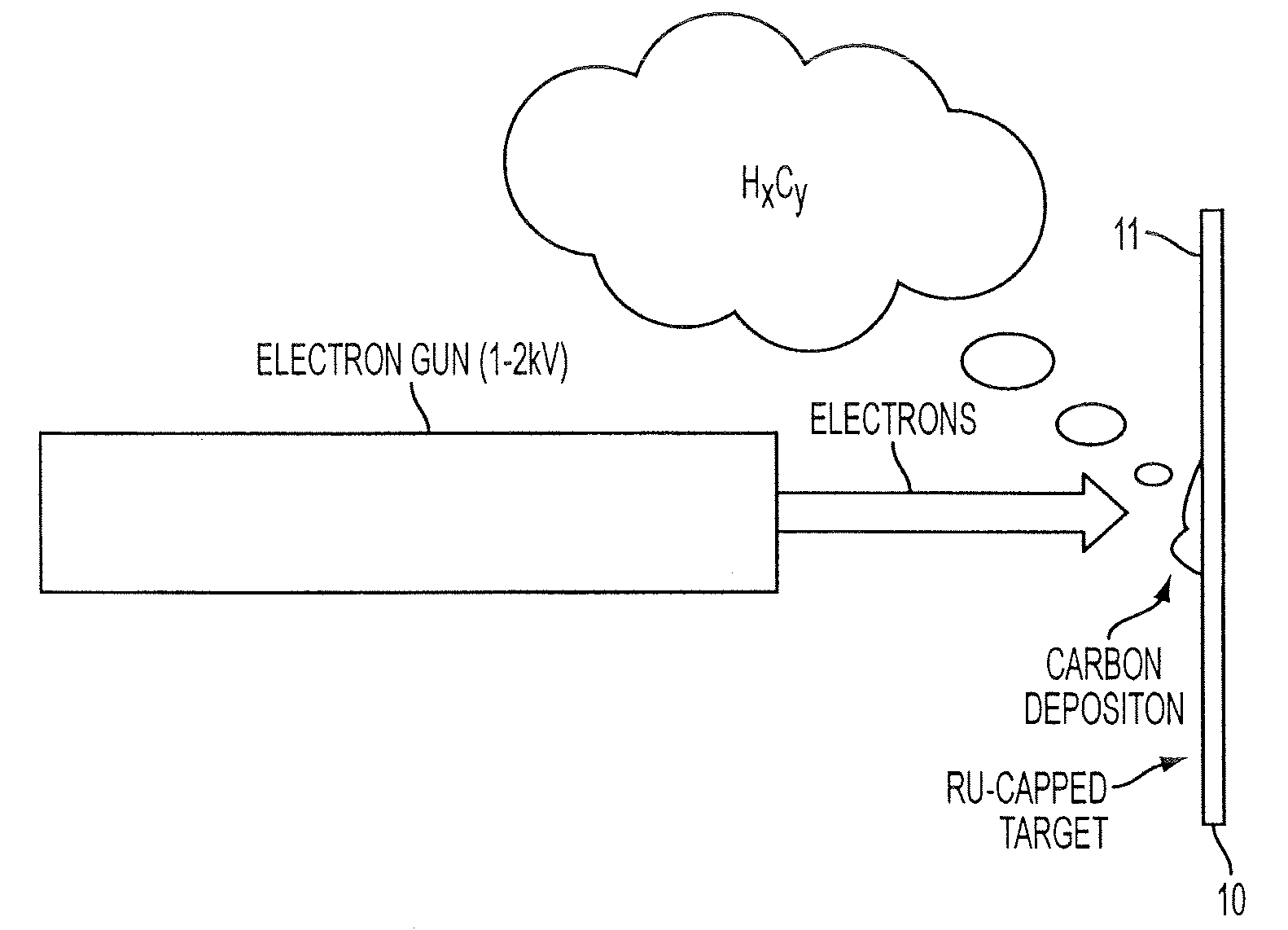
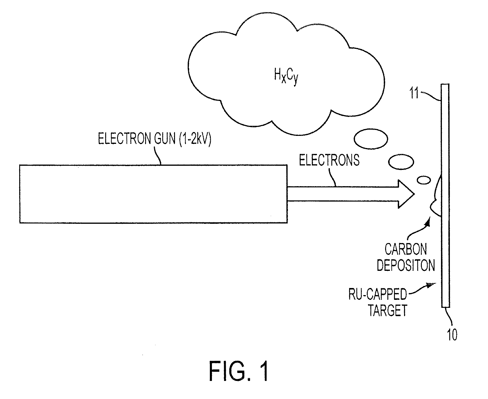
[0022]Embodiments of the present invention include carefully controlling the partial pressure of heavy hydrocarbons in an EUV lithography exposure tool, such as at a level of about 10−9 mbar to about 10−7 mbar, so that it is high enough to prevent oxidation of the reflective optical coatings but low enough to avoid rapid build up of a carbon film thereon. Carbon contamination results from hydrocarbon cracking by EUV radiation from the primary EUV source of the exposure tool.

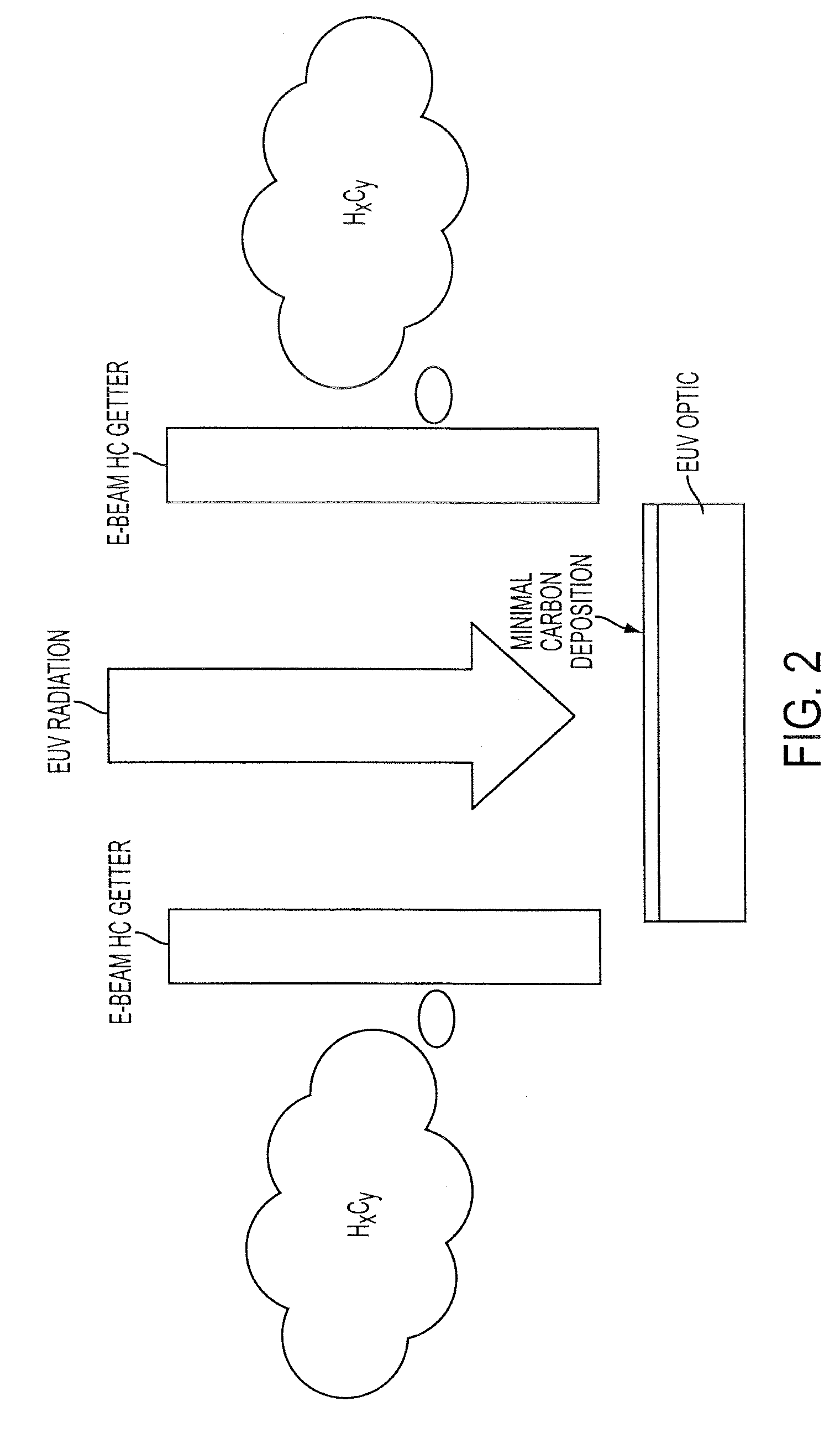
[0023]Embodiments of the present invention include positioning a hydrocarbon getter in a conventio...


PUM


Abstract

Carbon contamination of optical elements in an exposure tool is minimized by incorporating a hydrocarbon getter. Embodiments include EUV lithography tools provided with at least one hydrocarbon getter comprising a substrate and a high energy source, such as an electron gun or separate EUV source, positioned to direct an energy beam, having sufficient energy to crack heavy hydrocarbons and form carbon, on the substrate. Embodiments also include exposure tools equipped with a hydrocarbon getter comprising an energy source positioned to impinge a beam of energy on a quartz crystal thickness monitor, a residual gas analyzer, and a controller to control the electron-current and maintain the amount of hydrocarbons in the system at a predetermined low level.

Description

FIELD OF THE INVENTION[0001]The present invention relates to the efficient fabrication of semiconductor devices with accurate ultrafine design features. The present invention is particularly applicable to the efficient use of lithographic exposure devices, such as extreme ultraviolet (EUV) lithography devices, by minimizing downtime.BACKGROUND ART[0002]The dimensions of semiconductor device features relentlessly plunge into the deep sub-micron range challenging conventional fabrication capabilities. As critical dimensions shrink, it becomes increasingly more difficult to achieve high dimensional accuracy in an efficient manner with high manufacturing throughput. The minimum feature size depends upon the chemical and optical limits of a particular lithography system, and the tolerance for distortions. In addition to the limitations of conventional lithography, as dimensions shrink and memory capacity increases, manufacturing costs increase, thereby requiring advances in processing ai...

Claims


Application Information

Patent Timeline
IPC IPC(8): G03B27/52
CPCG03F7/70925G03F7/70916H01L21/0277
Inventor WOOD, II, OBERT R.
Owner ADVANCED MICRO DEVICES INC
Why Eureka
Try Eureka