
Fuel Cell

a fuel cell and cell technology, applied in the field of fuel cells, can solve the problems of reducing the power of the cell, affecting the anti-flooding property of the polyelectrolyte, and affecting the ion conductivity of the polyelectrolyte itself, so as to improve the anti-flooding property, stable gas supply, and suppress the growth of water drop enough to block the gas passage

Active Publication Date: 2009-01-22
PANASONIC CORP
View PDF0 Cites 16 Cited by
  • Summary
  • Abstract
  • Description
  • Claims
  • Application Information

AI Technical Summary

Benefits of technology

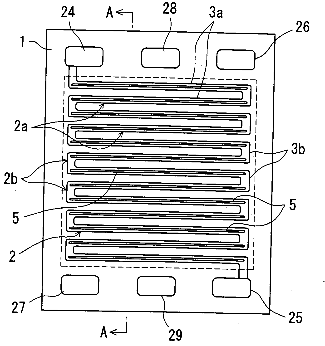
[0026]According to the present invention, in inner wall surfaces of the groove portions of the separators constituting the linear passage portions in the gas passages, water-retaining groove portions capable of retaining inside thereof at least part of water generated in the gas passages are formed in such a grooved configuration as to be substantially continuous along the linear passage portions. By adoption of this construction, as a water drop generated within the gas passage due to condensation of gas or the like makes contact with retained water within the water-retaining groove portions during its growth process, growth of the water drop enough to block the gas passage can be suppressed. Therefore, blockage of the gas passages due to such generation of water drops and their growth can be avoided with reliability, so that a stable gas supply can be realized. Thus, there can be provided a fuel cell capable of improving its anti-flooding property.

Problems solved by technology

In the case of a separator using a metal plate, since the metal plate is exposed to a high-temperature oxidative atmosphere, corrosion or dissolution of the metal plate may occur over long-time use.
Corrosion of the metal plate would cause the corroded portion to increase in electrical resistance, resulting in lowered power of the cell.
As a result, the ion conductivity of the polyelectrolyte itself would deteriorate.
For instance, in the case of lowered temperature or the like, the separator surface (inner wall surface of the groove portion) may be more liable to condensation, and it is practically impossible to completely eliminate such a phenomenon.
With occurrence of condensation, there is a problem of occurrence of a voltage instability phenomenon (flooding) that water drops generated by the condensation block the gas passages, causing deficiencies of fuel supply to the electrodes and the catalyst located downstream of the place of the blockage, in which case the voltage decreases gradually, and further, discharge of the water drops causes the blockage of the gas passages to be released, so that the fuel supply is recovered, in which case the voltage is increased.
As the material of the conventional-type fuel-cell separator, impermeabilized matters processed from graphite blocks, anti-corrosion metals, or liquid resin-containing matters obtained from an expanded graphite sheet molded laminate impregnated and hardened with liquid resin are usually employed, but separators made of such materials are poor at hydrophilicity.

Method used


Image

  • Fuel Cell
  • Fuel Cell
  • Fuel Cell

Examples


embodiment

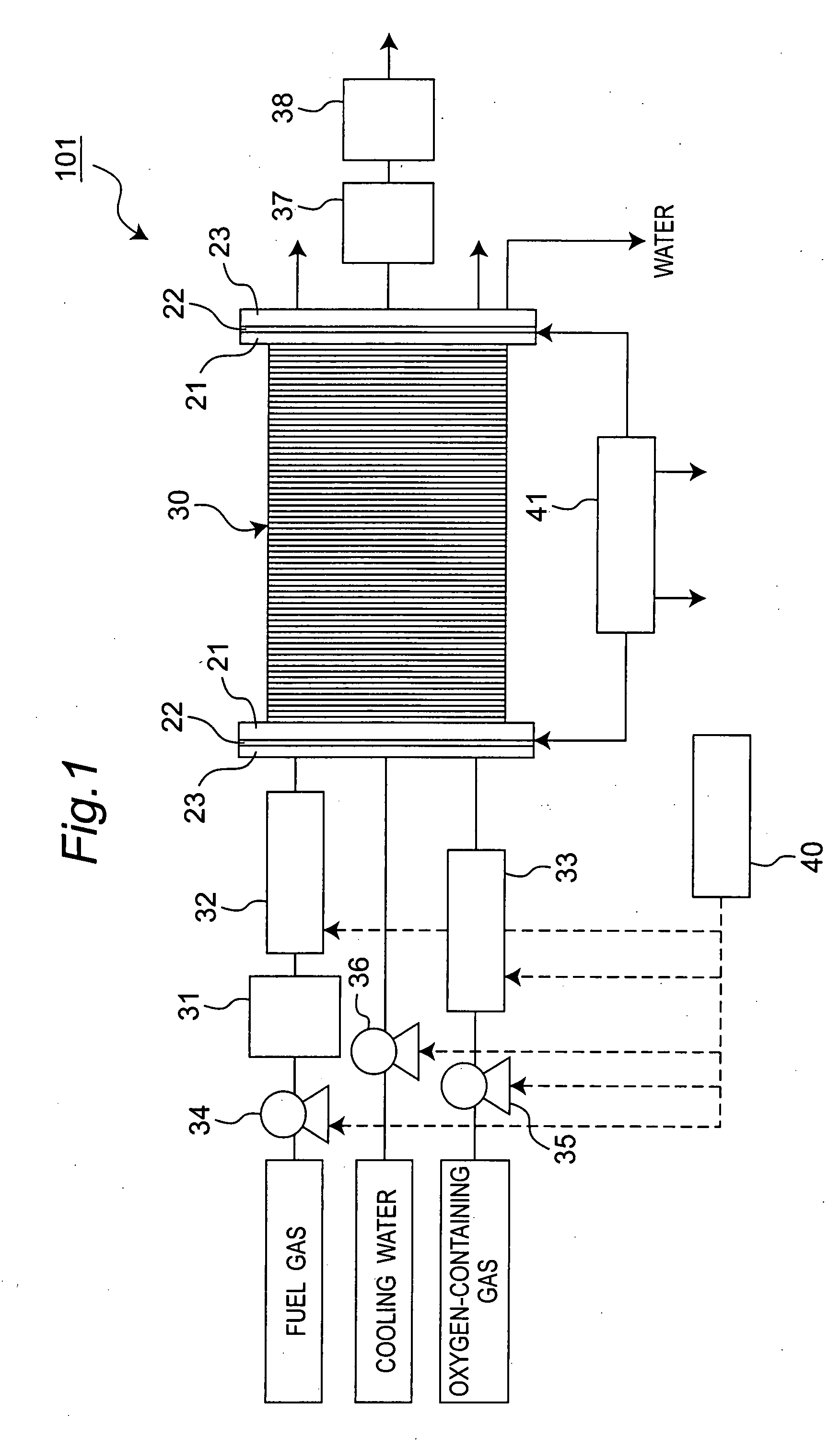
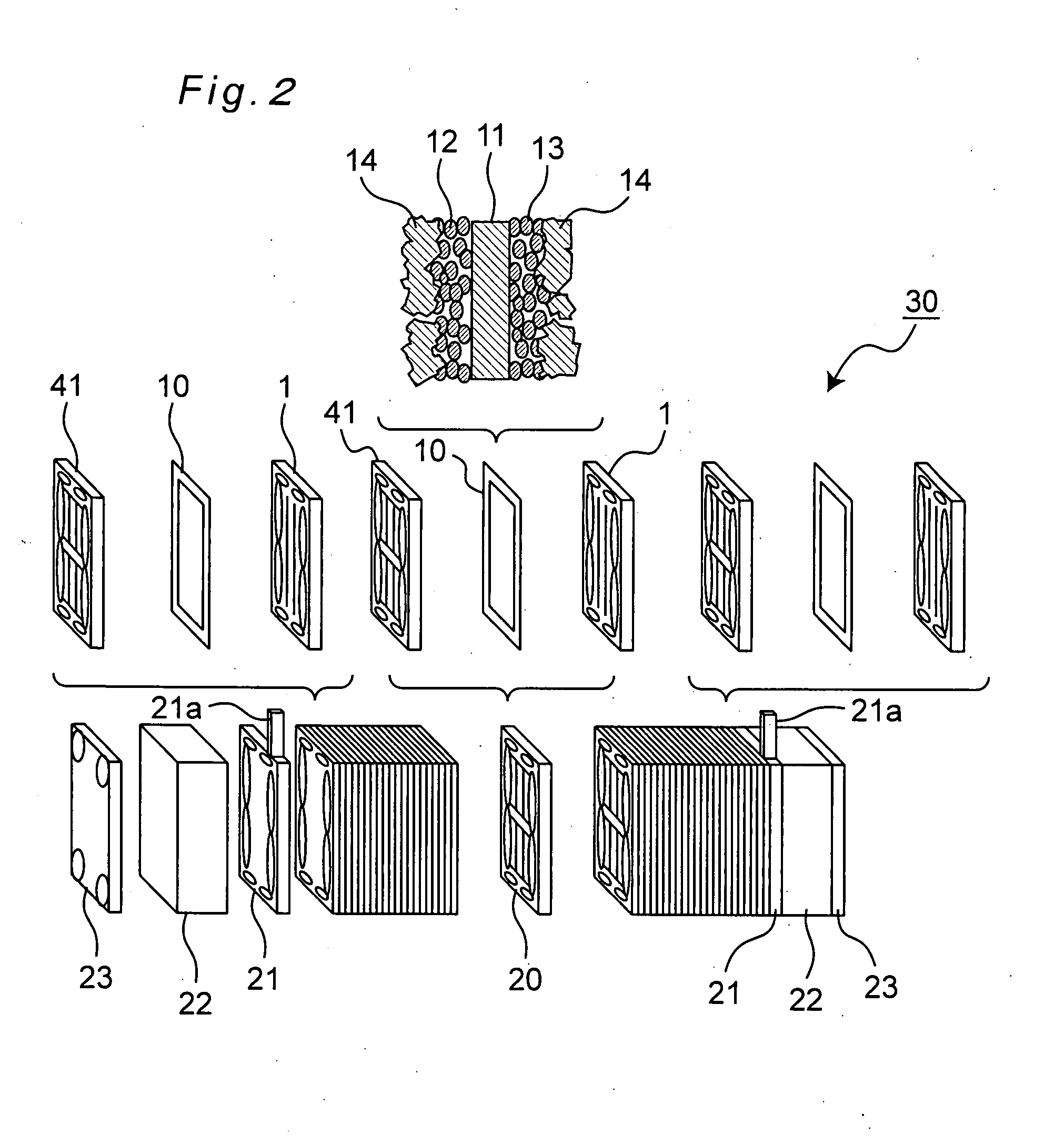
[0078]A schematic constructional view showing a schematic construction of a fuel cell according to one embodiment of the present invention is shown in FIG. 1. Also, a schematic exploded view of a fuel-cell stack (hereinafter, referred to as a stack) included in the fuel cell 101 shown in FIG. 1 is shown in FIG. 2.

[0079]The fuel cell 101 is a polymer electrolyte fuel cell (PEFC), as an example, which works to make a hydrogen-containing fuel gas and an oxygen-containing oxidizer gas such as air electrochemically react with each other to produce electric power, heat and water at the same time. As shown in FIG. 1, the fuel cell 101 includes a stack 30 having a layer-stacked structure in which a plurality of fuel-cell use cells (or unit cells) each having an anode-and-cathode pair of electrodes are connected in series, a fuel processor 31 for extracting hydrogen from fuel gas, an anode humidifier 32 for humidifying hydrogen-containing fuel gas extracted by the fuel processor 31 to improv...

examples

[0111]Next, several examples of the fuel cell of the above-described embodiment of the invention will be described below, in which effects of forming the small groove portions in the gas passages are explained.

first example

[0112]The fuel-cell stack according to First Example is a stack 30 which is formed as shown in FIGS. 3A and 3B as described above. Structure and manufacturing method of the stack 30 of this First Example are explained.

[0113]First, fabrication process for the MEA10 is explained. Acetylene black powder, on which 25 wt % of platinum particles having a mean particle size of about 30 Å was carried, was used as a catalyst for electrodes. Into a solution in which the catalyst powder was dispersed in isopropanol, a dispersion solution in which powder of perfluorocarbon sulfonic acid was dispersed in ethyl alcohol was mixed, by which a catalyst paste was obtained.

[0114]Meanwhile, a carbon nonwoven cloth (gas diffusion layer 14), which would serve as a base material for electrodes, was subjected to water repellency treatment. A carbon nonwoven cloth (made by Toray, TGP-H-120) having 14 cm×14 cm outer dimensions and a thickness of 36 μm was impregnated with a fluororesin-containing aqueous dis...


PUM


Abstract

In a fuel cell composed of a pair of separators with a membrane electrode assembly sandwiched therebetween, gas passages having a plurality of generally linear passage portions, and bent passage portions each of which makes one end portion of the linear passage portions communicated with the other end portion of the linear passage portions, are formed so as to be communicative from a gas introducing port to a discharge port. In inner wall surfaces of the groove portions of the separators constituting the linear passage portions, water-retaining groove portions capable of retaining inside thereof at least part of water generated in the gas passage are formed in such a grooved configuration as to be substantially continuous along the passage portion. As a water drop generated within the gas passage makes contact with retained water within the water-retaining groove portions, growth of the water drop is suppressed to avoid any blockage of the gas passage, by which the anti-flooding property is improved.

Description

TECHNICAL FIELD[0001]The present invention relates to a fuel cell using polyelectrolyte membranes which are used in portable power supplies, electric car-dedicated power supplies, home cogeneration systems and the like.BACKGROUND ART[0002]A fuel cell acts to make a hydrogen-containing fuel gas and an oxygen-containing oxidizer gas such as air electrochemically react with each other to produce electric power and heat concurrently. With regard to its structure, a catalytic reaction layer mainly composed of carbon powder carrying thereon a platinum-based metal catalyst is formed on both surfaces of a polyelectrolyte membrane which selectively transports hydrogen ions. A gas diffusion layer (e.g., carbon paper, carbon cloth, etc.) having both gas permeability and electron conductivity is formed on an outer surface of the catalytic reaction layer. This diffusion layer and the catalytic reaction layer (catalytic layer) are combined to provide electrodes. Generally, an electrode to which h...

Claims


Application Information

Patent Timeline
IPC IPC(8): H01M8/10H01M8/02H01M4/86
CPCH01M8/0258Y02E60/50H01M8/04156H01M8/026H01M8/0263H01M8/241H01M8/2457H01M8/2483H01M8/2484
Inventor MATSUMOTO, TOSHIHIROKUSAKABE, HIROKIKAWABATA, NORIHIKONAGAO, YOSHIKIYOSHIZAWA, NAOKO
Owner PANASONIC CORP
Learn More