Methods and apparatus for cell culture array

a cell culture array and array technology, applied in the field of molecular and cellular sample preparation and/or culturing and/or analysis, can solve the problems of inability to address the cellular length scale, labor/resource intensive current practices, and amenable to process control, etc., to achieve more uniform diffusion, easy manufacturing, and high fluid resistance

Active Publication Date: 2009-01-22
RGT UNIV OF CALIFORNIA
View PDF52 Cites 98 Cited by
  • Summary
  • Abstract
  • Description
  • Claims
  • Application Information

AI Technical Summary

Benefits of technology

[0057]In further example embodiments, one or more micro culture areas are connected to a medium or reagent channel via a grid of fluidic passages (or diffusion inlets or conduits), wherein the grid comprises a plurality of intersection micro high fluidic resistance passages. In one example, passages in the grid are about 1 to 4 μm in height, 25 to 50 μm in length and 5 to 10 μm in width, the grid allowing for more even diffusion between medium or reagent channels and the culture area and allowing for easier manufacturing and more even diffusion.
[0058]According to specific embodiments of the invention, the high fluidic resistanc

Problems solved by technology

However, most current practices are labor/resource intensive, not amenable to process control, cannot address cellular length scales, and prevent long-term continuous real-time monitoring or observation.
Furthermore, current cell culture practices have not provided fully satisfactory solutions to the challenge

Method used


Image

  • Methods and apparatus for cell culture array
  • Methods and apparatus for cell culture array
  • Methods and apparatus for cell culture array

Examples


example device

CONFIGURATIONS

2. Example 1

example experimental

Chamber

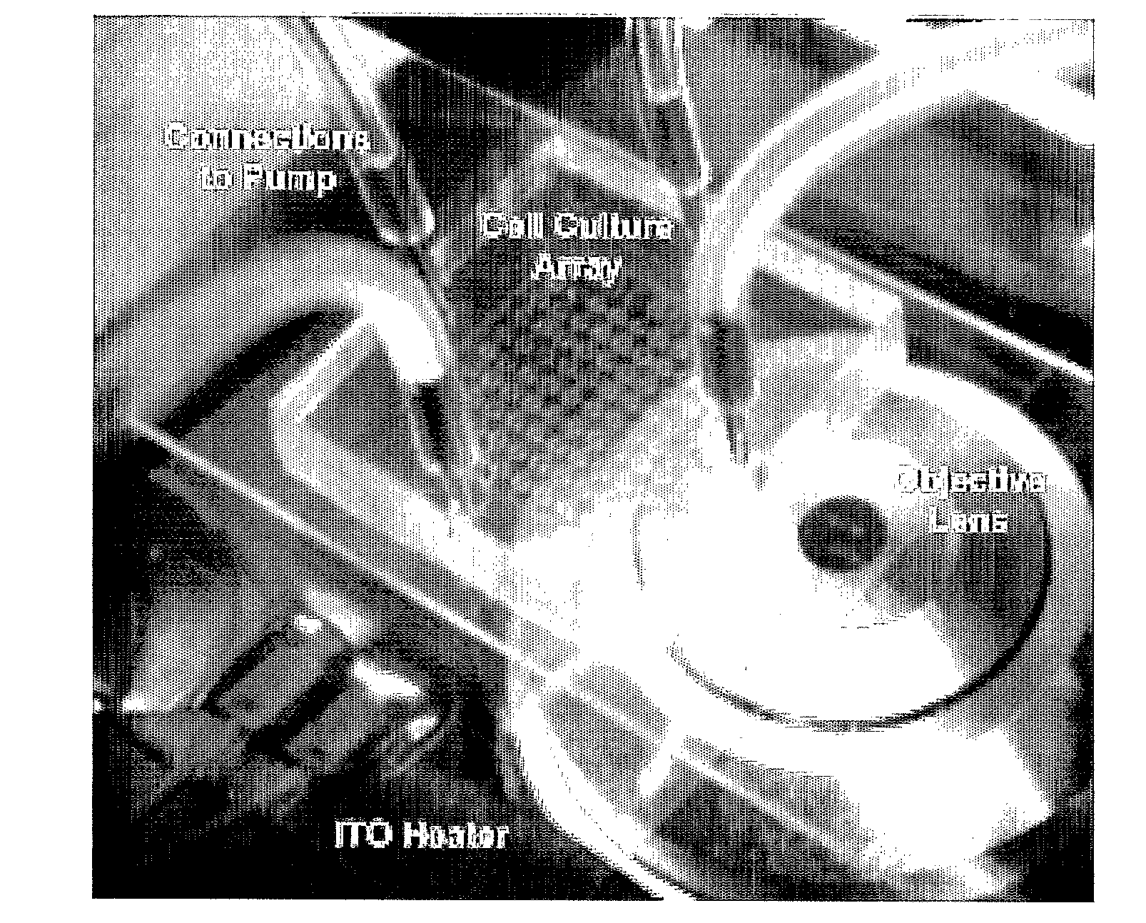
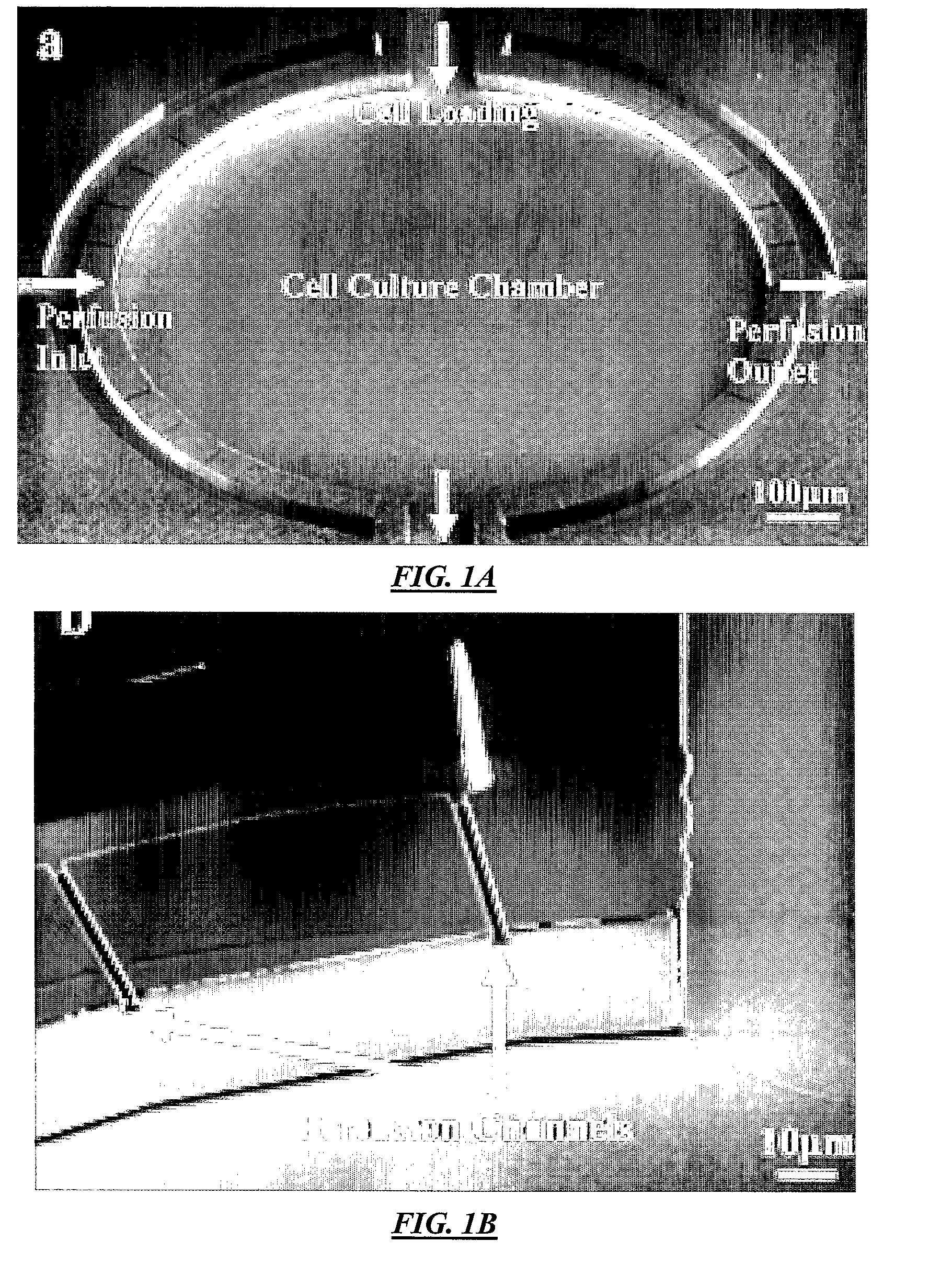
[0110]FIG. 1A illustrates a top view of an example cell culture device according to specific embodiments of the invention. This example has four ports: perfusion inlet, perfusion outlet, reagent loading, and waste, with the perfusion flow directed designated from left to right in the figure and reagent loading from top to bottom in the figure. As can be seen in the figure, the perfusion flow channels are separated from the main chamber by semi-circle-shaped perfusion channels at both the inlet (left) side and the outlet (right) side. Fluidic connection between these semi-circle-shaped channels and the culture chamber is made by the multiple high aspect ratio perfusion channels shown in the figure, which are approximately 1 / 10 to 1 / 50 the depth of the main channels and / or culture chamber. To prevent cells from flushing away during perfusion, approximately 2 μm height perfusion channels connect the perfusion inlets and outlets to the culture chamber. Because cells (typically >1...

example 2

3. Example 2

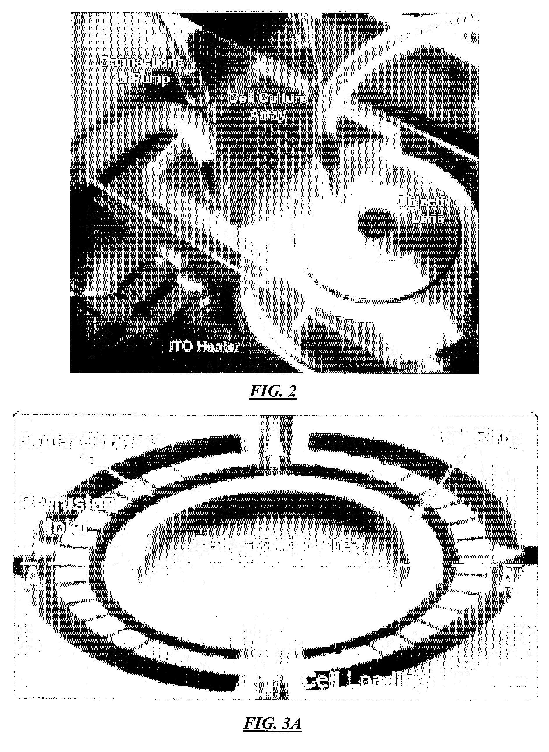
[0117]A further example nanoliter scale fluidically addressable microfluidic platform according to specific embodiments of the invention is described below. In a specific example, an addressable 6×6 array of eight nanoliter chambers is effective for long term continuous culture of the HeLa human cancer cell line with a functional assay of 36 different cellular microenvironments. In one optional construction. high aspect ratio soft lithography is used to create the high fluidic flow channels, though further study has shown that the same high fluidic resistance can be achieved using a diffusion structures with diffusion passages that have the same height a the main chamber and medium channels. In this example to further separate individual culture units from flow channels by a “C” shaped ring with a narrow gap along the base to effectively decouple cell growth regions from pressure-driven transport without the use of active valves. This design avoids problems encountered i...


PUM


Abstract

Method and systems that provide improved handling and/or culturing and/or assaying of cells, chemically active beads, or similar materials in microfluidic systems and microfluidic culture arrays.

Description

CROSS REFERENCE TO RELATED APPLICATIONS[0001]This application claims priority from provisional patent application 60 / 773,467 filed 14 Feb. 2006 and from provisional patent application 60 / 697,449 filed 7 Jul. 2005 both incorporated herein by reference for all purposes.COPYRIGHT NOTICE[0002]Pursuant to 37 C.F.R. 1.71(e), applicants note that a portion of this disclosure contains material that is subject to copyright protection (such as, but not limited to, diagrams, device photographs, or any other aspects of this submission for which copyright protection is or may be available in any jurisdiction.). The copyright owner has no objection to the facsimile reproduction by anyone of the patent document or patent disclosure, as it appears in the Patent and Trademark Office patent file or records, but otherwise reserves all copyright rights whatsoever.FIELD OF THE INVENTION[0003]The invention in specific embodiments relates generally to molecular and cellular sample preparation and / or cultu...

Claims


Application Information

Patent Timeline
IPC IPC(8): C40B50/18C40B60/14
CPCB01L3/502707B01L3/502746B01L2200/0689B01L2300/0816C12M29/10B01L2400/086C12M23/16C12M23/34B01L2400/0487C12M21/08C12M29/06B01L3/502715B01L3/502761B01L2200/027B01L2200/0647B01L2300/0627B01L2400/088B81B2201/05B81B2201/06B81C2201/019C12M41/46C12N5/0602
Inventor HUNG, PAUL J.LEE, PHILIP J.LEE, LUKE P.
Owner RGT UNIV OF CALIFORNIA
Why Eureka
Try Eureka