Fluoropolymer fine fiber

a technology of fluoropolymer and fine fiber, which is applied in the field of fine fiber nonwoven layers of fluoropolymer, can solve the problems of shifting the melting point and changing the solubility properties of materials, and achieves the effect of high stability to heat and pressur

Active Publication Date: 2009-02-05
DONALDSON CO INC
View PDF49 Cites 166 Cited by
  • Summary
  • Abstract
  • Description
  • Claims
  • Application Information

AI Technical Summary

Benefits of technology

[0025]An advantage of the invention is that electrospun webs such as the webs of the invention are relatively solvent free upon reaching the destination substrate. In terms of compatibility of the electrospun webs with the substrate, electrospinning can be advantageously employed using nearly any desirable substrate, as the solvents used will not interact with the substrate and cause dissolution, deterioration, weakening, or penetration of the substrate beneath the electrospun polymer. Thus, a wide range of substrates can be employed with the fluorocarbon fine fiber webs of the invention. Nonlimiting examples of the substrate on which the fluoropolymer fine fiber filtration layer can be formed include silicone impregnated cellulose, such as those that can be purchased from Ahlstrom Corporation of Bishopville, S.C., spunbond Reemay® from Fiberweb PLC of Old Hickory, Tenn., or meltblown polyester from Hollingsworth & Vose Company of East Walpole, Mass.
[0026]Once deposited on the substrate, the fluorocarbon fine fiber nonwoven webs of the invention can be crosslinked. Any technique generally known in the art can be used to crosslink the webs. Crosslinking imparts desirable properties to the webs of the invention, such as thermal and dimensional stability. As crosslinking can occur between different fibers in the nonwoven layer, a fiber can be covalently bonded to its adjacent neighbor. This renders the fluoropolymers themselves, as well as the pore sizes and fiber dimensions of the filter layer formed by the fine fiber webs of the invention, highly stable to the heat and pressure exerted in e.g. fuel filtration applications. The preferred technique for crosslinking the fluorocarbon fine fiber webs of the invention is the electron beam crosslinking.
[0027]Once formed and supported on a substrate, the fine fiber webs of the invention can advantageously be used, for example, to filter water and waterbased impurities from fuel such as jet fuel and diesel fuel.

Problems solved by technology

The inclusion of as little as 3% of HFP into polyvinylidene fluoride (PVDF) chains disrupts the polymer crystallinity noticeably, changing the solubility properties of the materials and shifting its melting point.

Method used


Image

  • Fluoropolymer fine fiber
  • Fluoropolymer fine fiber
  • Fluoropolymer fine fiber

Examples


example 1

[0101]A polymer solution was obtained by combining polymer and solvent in a 500 ml glass kettle with a 3-neck lid, to which mechanical stirring, a temperature probe, and a condenser were attached. The vessel was placed in a heating mantle and the temperature controlled at 45° C. under constant agitation until a uniform solution was obtained. The solution was cooled to room temperature before electrospinning.

[0102]The solution composition was 9 wt % Dyneon™ THV 220A (from Dyneon LLC of Oakdale, Minn.), in acetone. After the solution had reached room temperature, sodium iodide was added to a final concentration of 0.05% of the solids, with continuous agitation until the salt had completely dissolved.

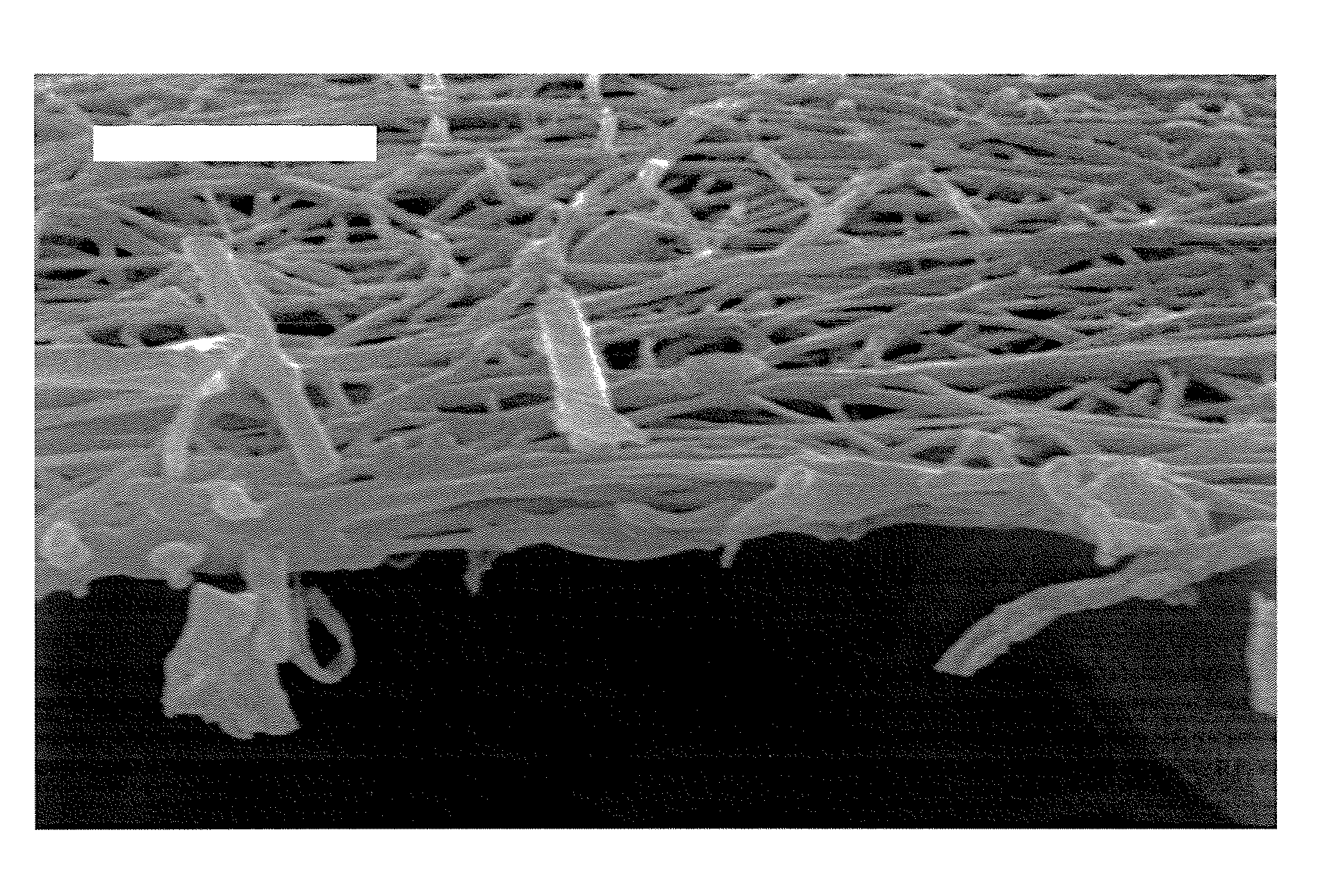
[0103]The solution was electrospun onto a silicone impregnated cellulose substrate (available as FF6168 from Hollingworth & Vose Company of East Walpole, Mass.) via a syringe, whereby flow was controlled through a syringe pump at 0.05 ml / min. The distance between the emitter (needle) and t...

example 2

[0105]A polymer solution was prepared as in Example 1 by combining polymer and solvent in a container with constant agitation until a uniform solution was obtained.

[0106]Solution composition was 9 wt % solids total, wherein the solids were about 50 / 50 Solef® 26106 / Solef 25108® (from Solvay S. A. of Brussels, Belgium), in acetone. After the solution had reached room temperature, sodium iodide was added to a final concentration of 0.05% of the solids, with continuous agitation until the salt had completely dissolved.

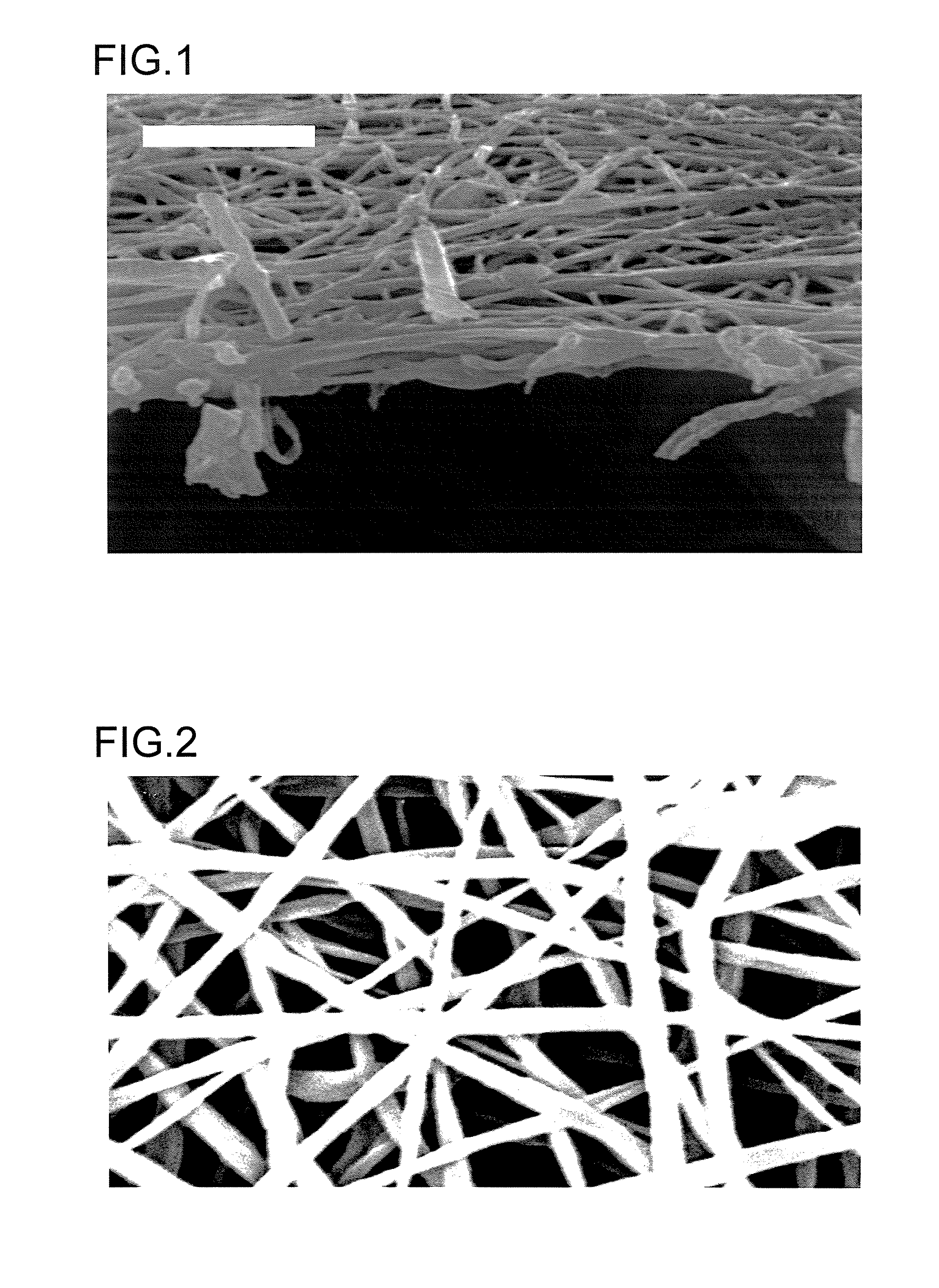
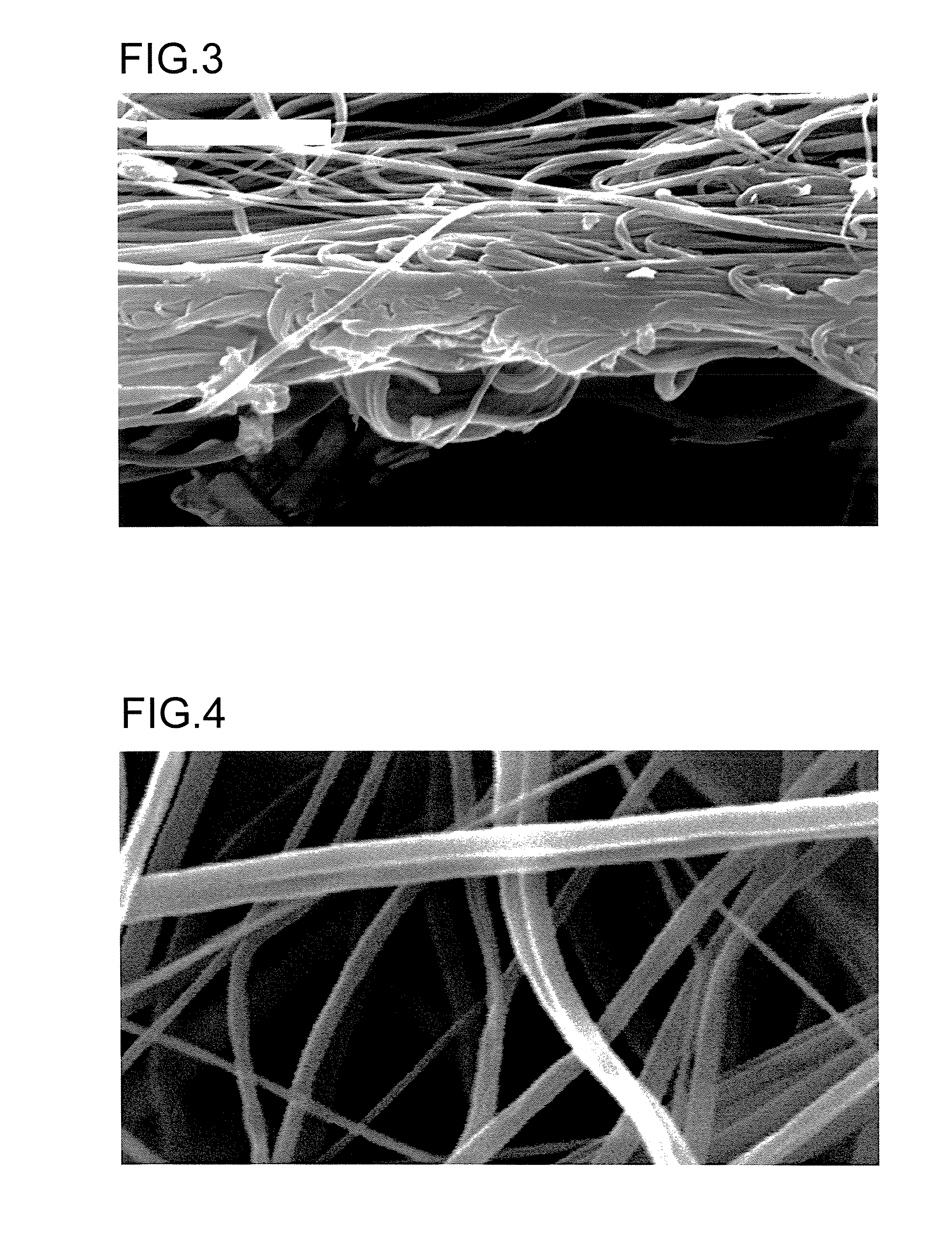
[0107]The solution was electrospun onto a silicone impregnated cellulose substrate (available as FF6168 from Hollingworth & Vose Company of East Walpole, Mass.) via a syringe, whereby flow was controlled through a syringe pump at 0.05 ml / min. The distance between the emitter and the substrate was fixed at 4 inches. The applied voltage was 25 Kvolts. The thickness of the resulting fine fiber mat was 3 μm, with an average fiber diameter of 0.3 μm.

[0108]FIGS. 3 and 4 show pho...

example 3

[0109]A polymer solution was obtained using the technique employed in Example 1 by combining polymer and solvent in a container with constant agitation until a uniform solution was obtained. The materials used, solution composition, and electrospinning conditions were identical to those of Example 2.

[0110]Longer fiber deposition time at the same rate as used in Example 2 resulted in a fine fiber mat with 30 μm thickness, with an average fiber diameter of 0.3 μm. FIGS. 5 and 6 show photo micrographs of the fibers produced under these conditions. FIG. 5 shows a 1000× cross section SEM micrograph of the fine fiber mat produced in Example 3. FIG. 6 shows a 10,000× magnification SEM micrograph of fine fibers produced as in Example 3. The discrete fine fiber structure of the invention is visible in these micrographs.


PUM

PropertyMeasurementUnit
thicknessaaaaaaaaaa
diameteraaaaaaaaaa
diameteraaaaaaaaaa

Abstract

A layer of fluoropolymer fine fiber can be made. The fine fiber can be made by electrospinning from a solvent or a solvent blend. The layers of the invention are useful in general filtration of fluid streams including gaseous and liquid streams. The fine fiber layers are also useful as hydrophobic filtration layers that can be used to separate water from a hydrocarbon stream.

Description

FIELD OF THE INVENTION[0001]The invention relates to fluoropolymer fine fiber nonwoven layers that can be used in filter applications. The invention also relates to fluoropolymer fine fiber nonwoven layers that can be used in separation of water from a fuel.BACKGROUND OF THE INVENTION[0002]Emulsified water contamination of fuel, particularly diesel fuel, jet fuel, biodiesel fuel, ethanol, butanol, or a blend thereof, is a serious concern for the operation of fossil fuel powered engines. Water can become stably entrained in such fuels, especially in diesel fuel formulations containing high concentrations of additives where the presence of water and waterbased impurities can cause fuel filter plugging, fuel starvation, damage of engine components by cavitation or corrosion, promotion of microbiological growth, and other problems.[0003]Separation of contaminant water from fuel has posed a particularly challenging problem. Industrial water-in-oil emulsions can be separated by gravity, c...

Claims


Application Information

Patent Timeline
Patent Type & Authority Applications(United States)
IPC IPC(8): C10L1/18B01D17/02B01D37/00B32B27/00D04H13/00H05B6/00D04H1/56B32B7/02C10L1/10
CPCB01D17/10B01D39/1623B01D46/546B01D2239/025D01D5/003D01D10/00Y10T428/268D01F6/32D06M10/00D06M2101/22D04H1/728D04H3/016Y10T428/24942D01F6/12Y10T442/68Y10T442/10Y10T442/60B01D17/02B01D17/04D01D5/0046
Inventor FERRER, ISMAELYANG, CHUANFANG
Owner DONALDSON CO INC
Why Eureka
Try Eureka