Inkjet recording method

a recording method and technology of inkjet, applied in the direction of duplicating/marking methods, inks, coatings, etc., can solve the problems of insufficient fixing strength, large amount of water remaining inside the image structure, and difficult to obtain sufficient fixing strength, so as to prevent non-uniformity in image strength, strong image structure, and high density of particle layers

Inactive Publication Date: 2009-04-02
FUJIFILM CORP
View PDF3 Cites 41 Cited by
  • Summary
  • Abstract
  • Description
  • Claims
  • Application Information

AI Technical Summary

Benefits of technology

[0023]In this aspect of the present invention, since the ink image is recorded onto a recording medium while being compressed in the transferring step, then high density of the particle layer can be achieved in the transferring step and therefore it is possible to obtain a stronger image structure.
[0024]According to the present invention, by preventing non-uniformities in the image strength caused by non-uniformities in drying resulting from nonuniform distri

Problems solved by technology

However, there may be a case where a large amount of water remains inside the structure of the image even after the heating process is carried out.
In this case, it is difficult to obtain sufficiently fixing strength since the residual water is not removed completely, even if a fixing process involving heating or the like is carried out.
For this reason, even if the polymer which is coating the pigment is sufficiently melted (softened), the volume of the gaps cannot be filled in by the flow of polymer and hence the fixing properties are insufficient.
It may be possible to reduce the gaps in the image by making the pigment particles themselves very fine; however, with a pigment which is covered with polymer, there are limits to the degree to which the particle diameter can be reduced.
Moreover, by reducing the particles to a very fine size, the interaction between the particles increases and since the surface layer is constituted by a polymer component, then the ink viscosity increases suddenly and the ejection characteristics become problematic.
However, the polymer micro-particles having a film forming capability typically have a minimum film forming temperature equal to or lower than room temperature, and therefore the formation of a film of the polymer micro-particles progresses in the vicinity of the nozzles during ejection, and

Method used


Image

  • Inkjet recording method
  • Inkjet recording method
  • Inkjet recording method

Examples


first embodiment

[0084]Next, an inkjet recording apparatus for implementing the inkjet recording method according to the present invention will be described.

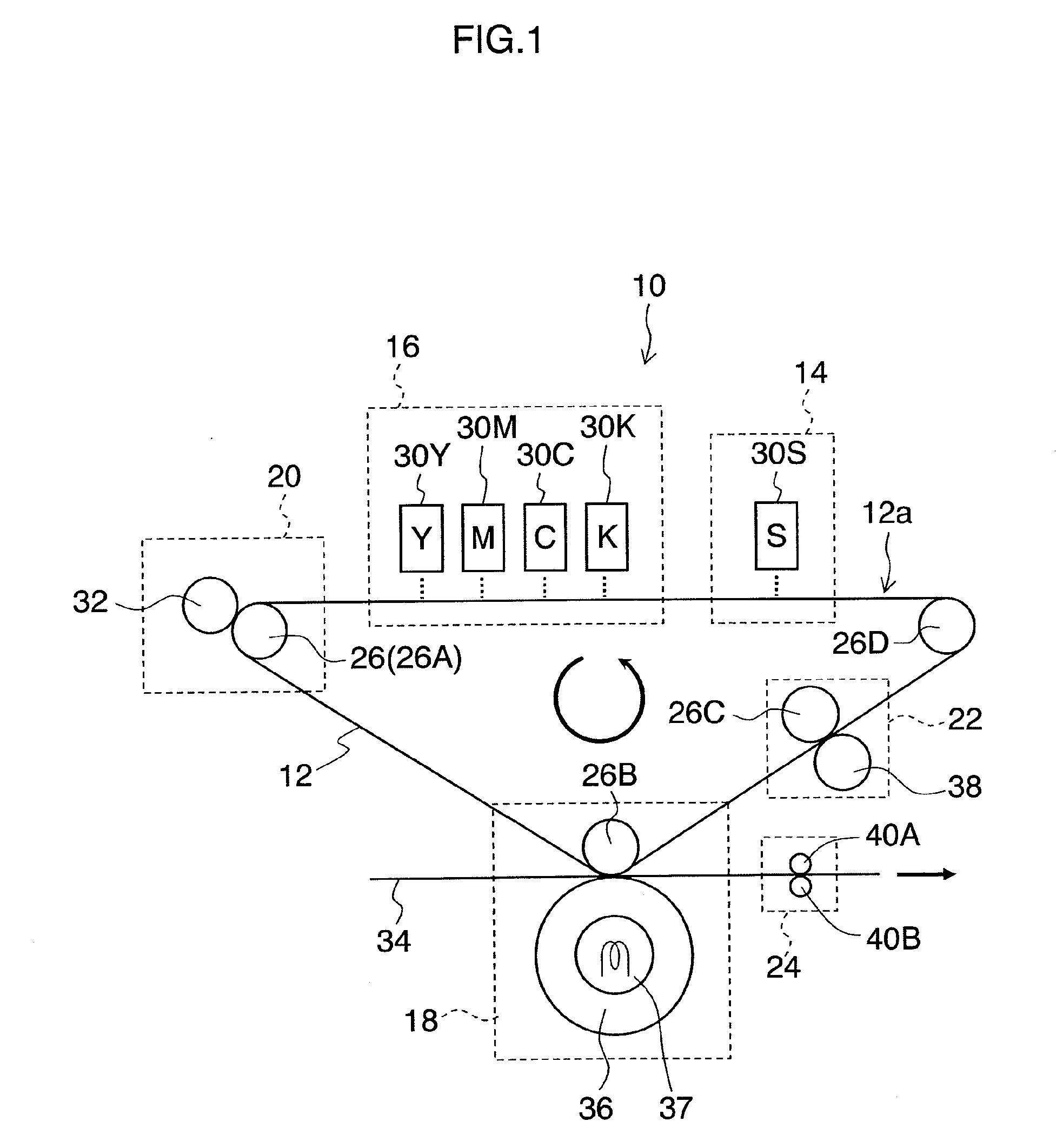
[0085]FIG. 1 is a diagram showing one example of the overall composition of an inkjet recording apparatus of a transfer type.

[0086]As shown in FIG. 1, the inkjet recording apparatus 10 principally comprises: an intermediate transfer body 12, a treatment liquid deposition unit 14, an ink ejection unit 16, and a transfer unit 18, and it is also provided with a solvent removal unit 20, a cleaning unit 22, and an image fixing unit 24.

[0087]The intermediate transfer body 12 is composed of an endless belt having a prescribed width, and the intermediate transfer body 12 is wound about a plurality of rollers 26. In the present embodiment, an example in which the four rollers 26A to 26D are used is described. The intermediate transfer body 12 is not limited to being an endless belt, and it may also employ a method where a cut-sheet intermediate transfer ...

second embodiment

[0121]Next, an inkjet recording method and apparatus of a direct recording type are described as a second embodiment.

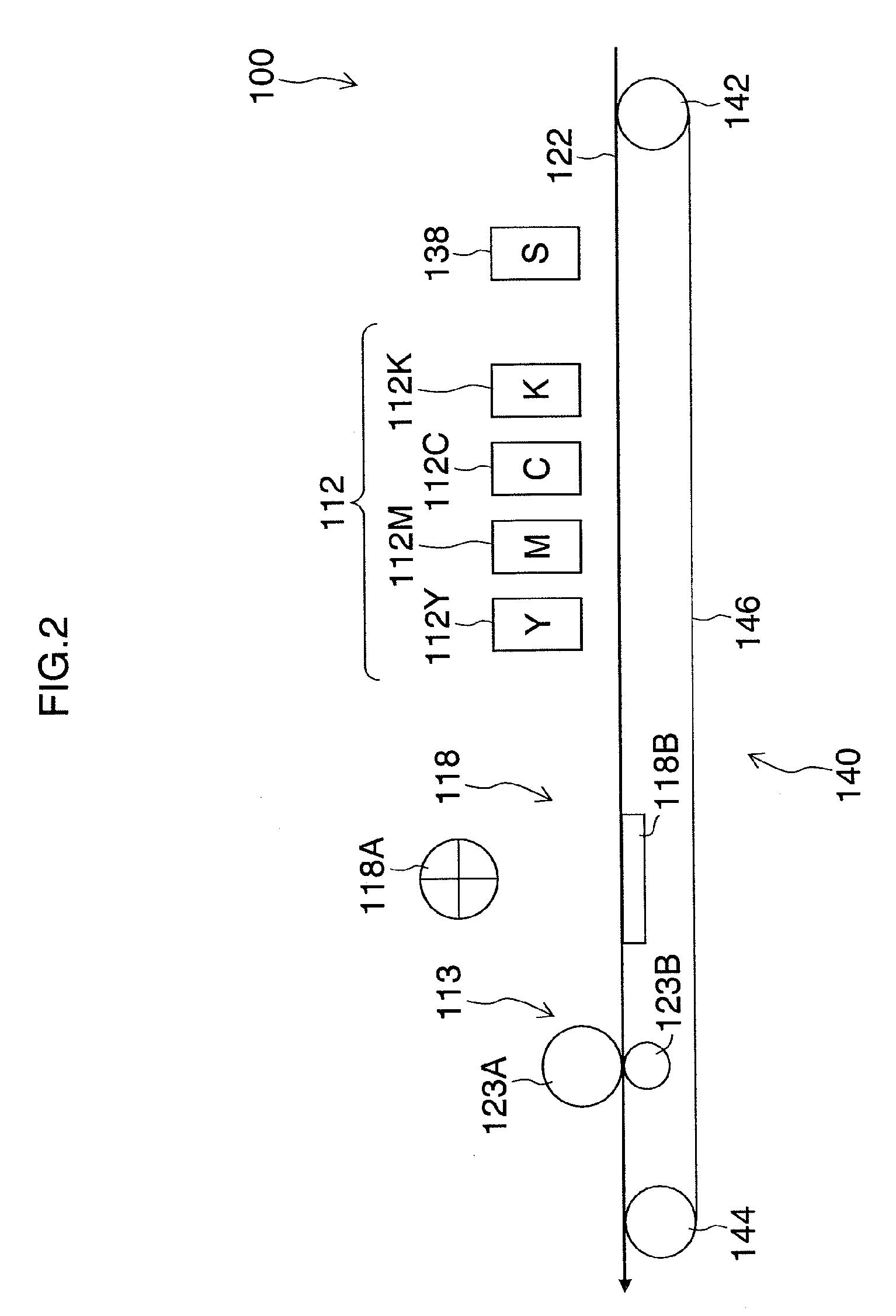
[0122]FIG. 2 is a general schematic drawing of an inkjet recording apparatus of a direct recording type.

[0123]The image recording apparatus 100 shown in FIG. 2 employs a direct recording method in which an image is formed directly onto a recording medium 122.

[0124]The inkjet recording apparatus 100 comprises: a treatment liquid deposition unit 138 which deposits treatment liquid onto a recording medium 122; an ink ejection unit 112 comprising heads 112K, 112C, 112M and 112Y which eject droplets of inks of respective colors of K, C, M and Y onto the recording medium 122 on which a treatment liquid layer has been formed by depositing treatment liquid; a solvent removal unit 118 comprising a hot air supply apparatus 118A and a heating panel 118B which remove residual solvent component that is remaining on the recording medium 122 onto which droplets of the inks of respec...

examples

[0135]The present invention is described more specifically below with reference to practical examples, but the present invention is not limited to these examples.

Manufacture of the Pigment Dispersion Liquid

(Pigment Dispersion A)

[0136]A solution comprising 6 parts by weight of styrene, 11 parts by weight of stearyl methacrylate, 4 parts by weight of styrene macromer AS-6 (made by Toa Gosei), 5 parts by weight of “Premmer” PP-500 (made by NOF Corp.), 5 parts by weight of methacrylic acid, 0.05 parts by weight of 2-mercapto ethanol, and 24 parts by weight of methylethyl ketone was prepared in a reaction vessel.

[0137]On the other hand, a mixed solution was prepared by introducing, into a titration funnel, 14 parts by weight of styrene, 24 parts by weight of stearyl methacrylate, 9 parts by weight of styrene macromer AS-6 (made by Toa Gosei), 9 parts by weight of “Premmer” PP-500 (made by NOF Corp.), 10 parts by weight of methacrylic acid, 0.13 parts by weight of 2-mercapotoethanol, 56 p...


PUM

PropertyMeasurementUnit
Temperatureaaaaaaaaaa

Abstract

An inkjet recording method includes the steps of: depositing droplets of an ink composition which contains at least water, organic solvent, coloring material particles and polymer micro-particles, one of the coloring material particles and the polymer micro-particles having a volume-average diameter that is 1.3 or more times larger than that of the other of the coloring material particles and the polymer-micro particles, the polymer micro-particles having a softening point (Tc) of 45° C. through 120° C. and a viscoelastic character that satisfies conditions of:
logG′1-logG′2≧2 and
logG′2≦5,
where G′1 is a storage elastic modulus of the polymer micro-particles at a temperature of T1 (° C.) that is lower than the softening point of the polymer micro-particles by 20° C., and G′2 is a storage elastic modulus of the polymer micro-particles at a temperature of T2 (° C.) that is higher than the softening point of the polymer micro-particles by 20° C.; removing a solvent component in the deposited droplets of the ink composition so that an ink image derived from the deposited droplets of the ink composition is left; and heating the ink image at a temperature not lower than the softening point (Tc) of the polymer micro-particles.

Description

BACKGROUND OF THE INVENTION[0001]1. Field of the Invention[0002]The present invention relates to an inkjet recording method, and more particularly, to an inkjet image recording method which suppresses the occurrence of image defects.[0003]2. Description of the Related Art[0004]In water-based inkjet recording method, it is preferable to remove the ink solvent component such as water or high-boiling-point organic solvent after recording in order to ensure durability of the image, such as fixing strength. For this reason, a fixing process has been known which ensures fixing strength by removing the water content by heating the recording medium onto which the image has been recorded, for instance. However, there may be a case where a large amount of water remains inside the structure of the image even after the heating process is carried out. In this case, it is difficult to obtain sufficiently fixing strength since the residual water is not removed completely, even if a fixing process ...

Claims


Application Information

Patent Timeline
IPC IPC(8): B05D5/00B41J2/01B41M5/00C09D11/00C09D11/322C09D11/328C09D11/54
CPCB41J2/01C09D11/322B41M5/0256B41J2002/012B41M5/0017B41M7/0018
Inventor HOUJOU, HIROAKI
Owner FUJIFILM CORP
Why Eureka
Try Eureka