
System and Method to Determine Chromatic Dispersion in Short Lengths of Waveguides Using a Common Path Interferometer

a technology of chromatic dispersion and path interferometer, which is applied in the direction of measurement devices, instruments, material analysis through optical means, etc., can solve the problems of intersymbol interference, no longer being able to determine whether, and reducing the number of bits that can be transmitted

Inactive Publication Date: 2009-04-16
GALLE MICHAEL +2
View PDF6 Cites 12 Cited by
  • Summary
  • Abstract
  • Description
  • Claims
  • Application Information

AI Technical Summary

Benefits of technology

[0033]The main problem in implementing a Michelson interferometer is that the arms of the coupler cannot be balanced

Problems solved by technology

Pulse broadening causes adjacent bits to overlap and leads to intersymbol interference.
Intersymbol interference occurs when a pulse is broadened beyond its allocated bit slot to such an extent that it begins to overlap with adjacent bits and it is no longer possible to determine whether or not a specific bit contains a 1 or a 0.
As a result of intersymbol interference the allocated bit slots must be widened and this effectively lowers the number of bits that can be transmitted in a given period of time and reduces the system bandwidth.
Thus accurate knowledge of the dispersion in a waveguide cannot be made by simple knowledge of the material dispersion but must include the effect of the waveguide.
As a result either the dimensions of the waveguide must be known to a high degree of accuracy so that the waveguide dispersion can be calculated (which is not easy since fabrication processes are hardly perfect) or the dispersion must be measured empirically.
One of the main problems with the TOF technique is that it generally requires several kilometres of fiber to accumulate an appreciable difference in time for different wavelengths.
Another issue with the TOF technique when the pulse broadening is measured directly is that the pulse width is affected by changes in the pulse shape which leads to errors in the measurement of the second order dispersion parameter.
The first is that it is expensive to implement since the components required such as an RF analyzer and a tunable laser, are costly.
The second is that its precision is limited by both the stability and jitter of the RF signal.
MPS has several limitations on the minimum device length that it is capable of characterizing.
Therefore it is not desirable for the characterization of specialty fibers or gain fibers, of which long fiber lengths are expensive to acquire or not available.
Also, when fiber uniformity changes significantly along its length, the dispersion of a long span of fiber cannot be used to accurately represent that of a short section of fiber.
The main disadvantage of temporal interferometry is that it is susceptible to noise resulting from both translation inaccuracy and vibration of the optics in the variable path.
Another problem with this technique is that a second derivative of the phase information must be taken to obtain the second order dispersion parameter which means that it is less accurate than a method that can obtain the dispersion parameter directly.
The main issue with this form of spectral interferometry, however, is that the dispersion parameter is not determined directly but rather via a second order derivative of the phase information with respect to wavelength.
Therefore, like temporal interferometry, this general unbalanced form of spectral interferometry is not as accurate as the method capable of measuring the dispersion parameter directly which is now discussed.
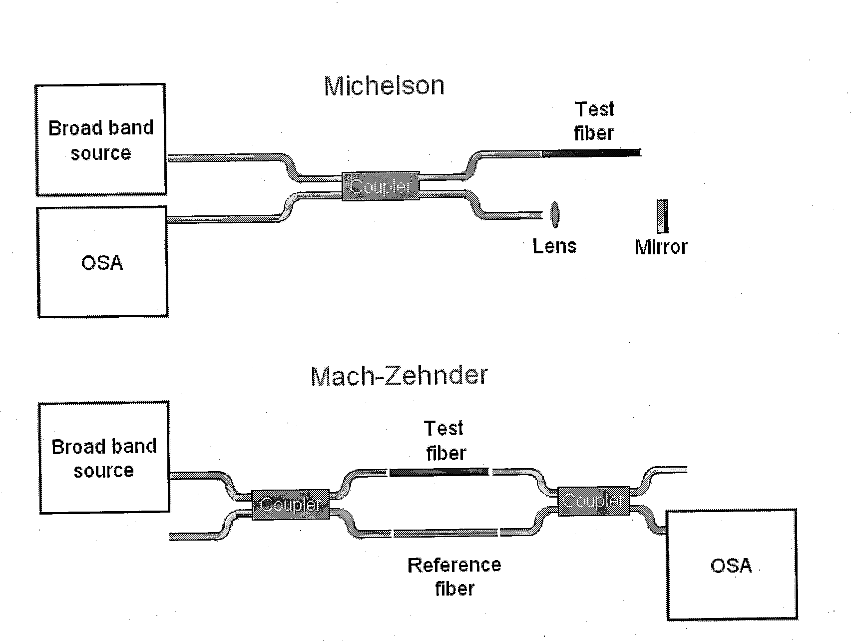
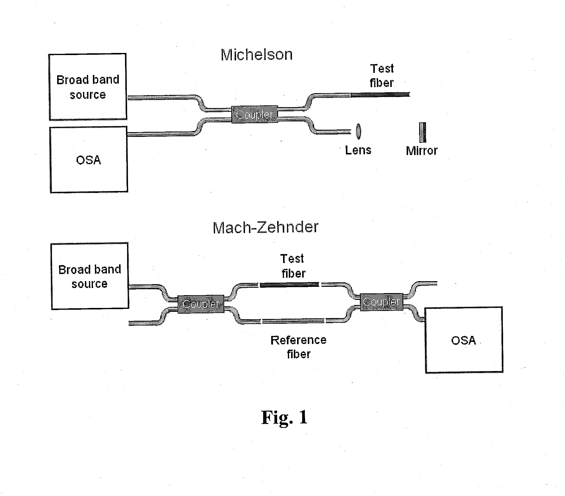
The main disadvantage of this configuration is that, for this to work, two types of path balancing must occur simultaneously.
The main problem in implementing a Michelson interferometer is that the arms of the coupler cannot be balanced exactly and as a result the effect of the extra set of reflections produced at the coupler facets cannot be removed.
Though accurate effective index measurement can be done using a coupling grating with a known period, this method is destructive, and cannot be used to measure over a large bandwidth, and thus cannot measure quadratic dispersion.

Method used


Image

  • System and Method to Determine Chromatic Dispersion in Short Lengths of Waveguides Using a Common Path Interferometer
  • System and Method to Determine Chromatic Dispersion in Short Lengths of Waveguides Using a Common Path Interferometer
  • System and Method to Determine Chromatic Dispersion in Short Lengths of Waveguides Using a Common Path Interferometer

Examples


experimental verification

2: Experimental Verification

2.1 Experimental Process

[0060]The first step in the experiment is to set up the Single Arm Interferometer and to assemble the control and data acquisition hardware. The second step in the experiment is to test the technique by using it to measure the dispersion of fibers for which the dispersion curves are known or that can easily be measured using conventional techniques.

[0061]The Single Arm Interferometer measured the dispersion parameters for two different samples: 6 mm twin-hole fiber and 2.88 mm AlGaAs waveguide. The fiber sample consists of two air holes 45 μm radius each and a 4 μm radius Ge doped silica core located closer to one of the holes. The waveguide is a 1.5 μm Al0.18Ga0.82As core layer, surrounded above and below by Al0.24Ga0.76 as cladding layers (1.5 μm above, and 4.0 μm below), grown on a GaAs substrate. The in-plane confinement was achieved by photolithography and dry etching of 3.5 μm wide and 2 μm deep ridge. The maximum sub-band wi...


PUM


Abstract

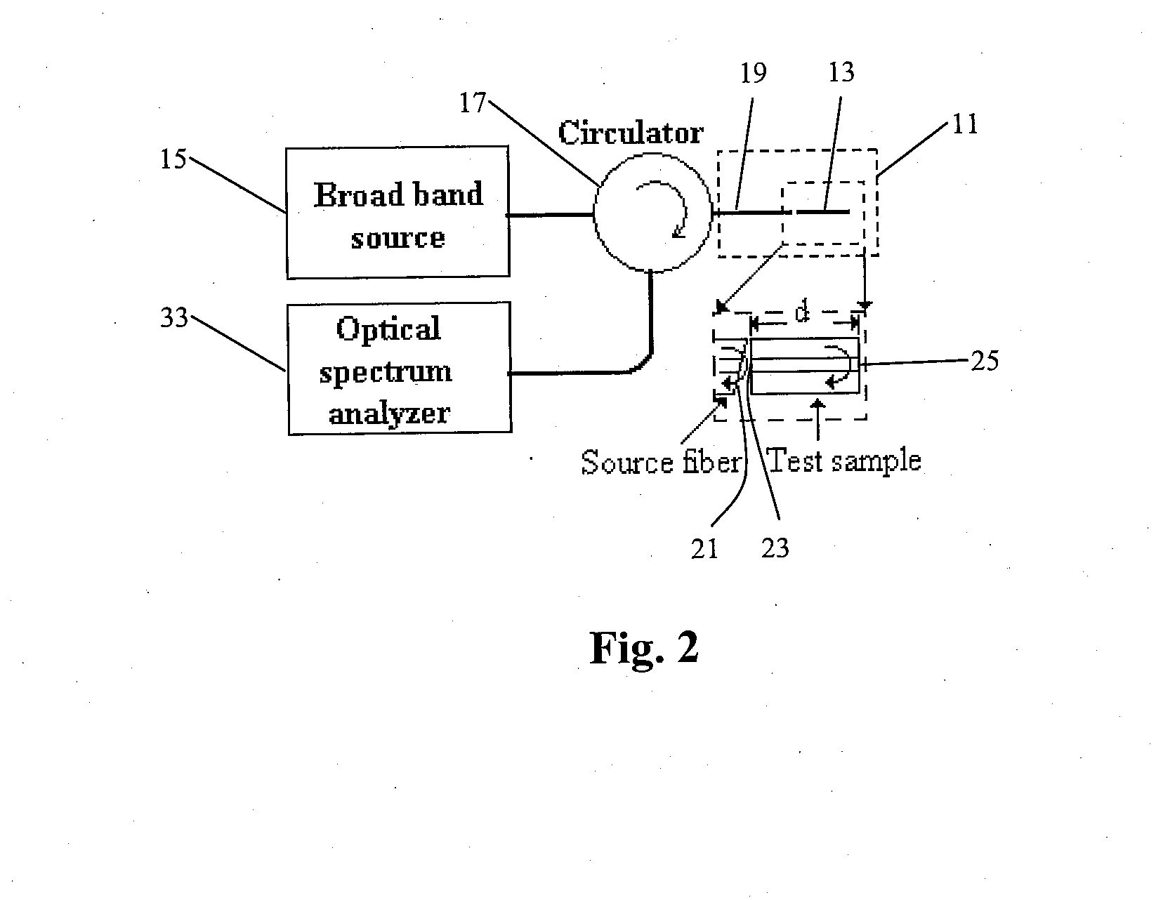
The present invention relates to a system and method to determine chromatic dispersion in short lengths of waveguides using a two wave interference pattern and a common path interferometer. Specifically the invention comprises a radiation source operable to emit radiation connected to a means for separating incident and reflected waves; the means for separating incident and reflected waves possessing an output arm adjacent to a first end of the waveguide; and the means for separating incident and reflected waves further connected to an optical detector operable to record an interference pattern generated by a reflected test emission from the radiation source. The interference pattern consists of two waves: one reflected from a first facet of a waveguide and the second reflected from a second facet of the same waveguide.

Description

FIELD OF THE INVENTION[0001]This invention relates to a system and method to determine chromatic dispersion in short lengths of waveguides using a two wave interference pattern and a common path interferometer.BACKGROUND OF THE INVENTION[0002]One of the main components in a photonic device is a waveguide such as an optical fiber which serves as a low-loss medium for light transmission. An important characteristic of a waveguide such as optical fiber is the dispersion that light experiences as it travels inside the fiber. Dispersion is the phenomenon that causes different frequencies of light to travel at different velocities. The phenomenon of dispersion is commonly observed through the spreading of light by a prism. When white light, which contains a broad spectrum of frequencies, enters a prism the different wavelengths are bent at different angles since each frequency sees a different index of refraction, a phenomenon first quantified by Newton in the 17th century. Inside a fiber...

Claims


Application Information

Patent Timeline
IPC IPC(8): G01B9/02
CPCG01M11/3163
Inventor GALLE, MICHAELMOHAMMED, WALEEDQIAN, LI
Owner GALLE MICHAEL
Learn More