
Method for inducing hypothermia

a hypothermia and hypothermia technology, applied in the field of hypothermia induction, can solve the problems of rapid and significant cooling, less than 2-4% survival rate of cardiac arrest patients, and tissue damage postponement of hypothermia, etc., to achieve rapid induction, improve patient outcome, and high protective

Inactive Publication Date: 2009-05-14
UNIVERSITY OF CHICAGO
View PDF25 Cites 30 Cited by
  • Summary
  • Abstract
  • Description
  • Claims
  • Application Information

AI Technical Summary

Benefits of technology

This approach enables rapid induction of hypothermia in cardiac arrest patients, significantly improving survival chances by effectively cooling the brain and heart within minutes, thereby reducing tissue injury from ischemia and reperfusion.

Problems solved by technology

It is well known that hypothermia can postpone damage to tissues caused by inadequate blood flow and oxygen deprivation.
Despite widespread use of basic life support and advanced cardiac life support by paramedics, survival of cardiac arrest patients is usually less than 2-4%, in large part because cells of the brain and the heart begin to die within minutes following global ischemia, or inadequate blood flow.
However, rapid and significant cooling (within 10 minutes, and to a temperature of 34° C. or less) of a patient without blood flow in a pre-hospital setting has been unachievable.
External cooling methods have not been found effective in achieving the desired rates of cooling.
Several studies by the applicants highlight the fact that current techniques of surface cooling alone are not effective for the rapid induction of hypothermia.
This results in a cooling rate of less than 6° C. per hour, not rapid enough for protective use during cardiac arrest.
), achieving a nearly maximally effective surface heat transfer coefficient, the lack of blood flow during cardiac arrest prevents achieving the desired protective core cooling rates.
The physics of thermal heat-transfer creates a formidable challenge to rapid cooling of a human with little or no circulation.
This is particularly problematic since the brain and heart are the targets of the cooling process.
The difficulty is that without a pulse or adequate perfusion, there is very little transfer of heat from the deeper tissues to the superficial tissues.
Unfortunately, the speed of cooling with these techniques is too slow to avoid a lethal outcome due to ischemic reperfusion injury to vital organs, including the heart and brain.

Method used


Image

  • Method for inducing hypothermia
  • Method for inducing hypothermia
  • Method for inducing hypothermia

Examples


example 1

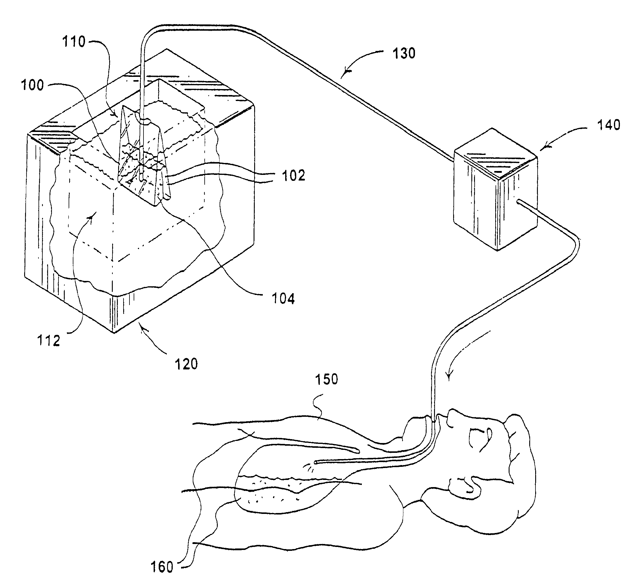
[0056]The first example is an ice slurry made from medical grade sodium chloride saline solution. This slurry is used to cool major blood vessels which flow to the head and the heart as with the aortic flush and neck injections described above. The movement of the slurry and the transport of cooled blood into the critical zones is enhanced by chest compressions.

[0057]The sodium chloride in aqueous solution serves as a freezing point depressant and alters the nature of the ice crystals formed in solution when the solution is cooled to its freezing point. Using about a 0.9% saline solution, a slurry is formed in a saline solution confined in a container or in a saline solution directly in a plastic medical injection bag ensuring sterility for the patient and convenience for the suppler. The solution is cooled to the point where ice crystals form. The freezing point for a 0.9% concentration, for example, of sodium chloride is −0.3° C. In contrast to pure water, the saline solution in t...

example 2

[0065]In another embodiment, cooling of the heart is achieved by charging the lungs with a phase-change slurry. Due to the almost intimate contact of the lungs with one side of the heart, charging the lungs greatly improves the rate of cooling of the heart. One example of a phase-change ice slurry used for the lungs is in the form of liquid perfluorocarbon or sodium chloride solution either of which may be used as the carrier of ice particles into the lungs. When oxygenated, the sodium chloride solution or perfluorocarbon liquid can also serve as a liquid ventilator or oxygen transporter.

[0066]During cardiac arrest, the lungs are effectively a dead air space and behave as an insulating layer that significantly reduces heat transfer to and from the heart, impeding cooling applied externally to the chest. Because the heart lies immediately behind the lungs, with only a thin membrane layer separating the two regions, the heart can be more rapidly cooled by using a coolant delivered to ...

example 3

[0083]Ham: surface cooling / no blood flow

[0084]As a means of obtaining an indication of a cool-down rate associated with external surface cooling only of a large tissue mass of size and surface area similar to the head, an experiment was conducted on a 9.8 pound ham (shank portion) with an imbedded bone mass. The ham was cooled down from an initial temperature of 29.4° C. to 16.7° C. in 30 minutes by direct full immersion in a tightly packed ice slush water bath at 0° C. with a thermocouple imbedded 3.5 inches into the thickest part of the ham. The resulting core cool-down rate was 0.42° C. / min. These results confirm that surface cooling only, in the absence of blood flow, falls far short of achieving the desired cooling.

[0085]FIG. 5 shows the results of the sphere heat conduction model applied to the ham compared with the measured ham core temperature history based on a sphere of radius b=3.5 inches for thermal diffusivities ranging from 1.5 to 5.0×10⁻⁷ m2 / S.


PUM


Abstract

Systems for phase-change particulate slurry cooling equipment and methods to induce hypothermia in a patient through internal and external cooling are provided. Subcutaneous, intravascular, intraperitoneal, gastrointestinal, and lung methods of cooling are carried out using saline ice slurries or other phase-change slurries compatible with human tissue. Perfluorocarbon slurries or other slurry types compatible with human tissue are used for pulmonary cooling. And traditional external cooling methods are improved by utilizing phase-change slurry materials in cooling caps and torso blankets.

Description

RELATED APPLICATIONS[0001]This application is a continuation of U.S. patent application Ser. No. 11 / 124,958 filed May 9, 2005, now U.S. Pat. No. 7,422,601, issued Sep. 9, 2008, which is a continuation of U.S. patent application Ser. No. 10 / 162,442, filed Jun. 3, 2003, by Lance B. Becker et al., entitled “Method for Inducing Hypothermia,” now U.S. Pat. No. 6,962,601 issued Nov. 8, 2005, which is a continuation-in-part of U.S. patent application Ser. No. 09 / 586,576, filed Jun. 2, 2000, by Kenneth E. Kasza, entitled “Method And Apparatus For Producing Phase Change Ice Particulate Saline Slurries,” now U.S. Pat. No. 6,413,444 issued Jul. 2, 2002, and U.S. patent application Ser. No. 09 / 632,195, filed Aug. 2, 2000, by Lance B. Becker, Terry Vanden Hoek, and Kenneth E. Kasza, entitled “Method For Inducing Hypothermia,” now U.S. Pat. No. 6,547,811 issued Apr. 15, 2003, each of which claims the benefit of priority under 35 U.S.C. § 119(3) to U.S. Provisional Application No. 60 / 146,753, file...

Claims


Application Information

Patent Timeline
Patent Type & Authority Applications(United States)
IPC IPC(8): A61F7/12A61F7/00A61F7/02C09K5/06F25C1/00
CPCA61F7/02A61F7/12F25C1/00C09K5/066A61F2007/0292
Inventor BECKER, LANCE B.HOEK, TERRY VANDENKASZA, KENNETH E.
Owner UNIVERSITY OF CHICAGO
Learn More