Centralized base station system based on advanced telecommunication computer architecture platform

a technology of telecommunications computer and platform, applied in the field of mobile communication system base station technique, can solve the problems of sharing optimization, unoptimized, and difficult to solve the coverage problem of wireless network with conventional bts technology, and achieve the effects of improving usability, high throughput, and speed

Inactive Publication Date: 2009-06-11
UTSTARCOM TELECOM CO LTD
View PDF6 Cites 265 Cited by
  • Summary
  • Abstract
  • Description
  • Claims
  • Application Information

AI Technical Summary

Benefits of technology

[0059]In the base station system structure according to the present invention, by adopting the Ethernet dual star link provided by the ATCA BASE interface as user data flow transmission carrier between the base station controller interface module and the baseband processing module, and adopting the high speed serial dual star link provided by the ATCA FABRIC interface to meet requirements of high speed and high throughput required by baseband data flow transmission between the baseband processing module and the remote radio frequency interface module, and between the baseband processing module and the local radio frequency module, usability of the system is increased. By taking advantage of large area of the ATCA single board, the Ethernet switch function of BASE interface, the baseband data flow switch function of FABRIC interface and the clock distribution function are integrated in one hardware module, reducing the types of modules and saving the slots of shelves. The larger single board area also allows a single baseband processing module to accommodate more processing resources.

Problems solved by technology

In the mobile communication system, there are wireless network coverage problems that are more difficult to solve with conventional BTS technology, such as indoor coverage of high-rise buildings, coverage hole, or the coverage of shadow zone.
However, in the existing centralized base station system, its interconnection architecture restricts such sharing optimization.
1) Binding the baseband processing resources and the remote radio frequency units together, such that the baseband processing resource only serve the bound remote radio frequency unit. This is apparently not optimal.
2) Establishing physical connections between the baseband processing resources and the remote radio frequency units according to fixed correspondence (such as one to one). An extreme case is to apply a physical all-interconnecting (Mesh) connection relation between the baseband processing resources and the remote radio frequency unit. But this manner is only applicable to small base station, and still belongs to the above binding manner in substance, nothing but implementing the binding through physical connections. The cost of all-interconnecting is very high, and cannot be implemented when the base station is larger. Furthermore, reducing the interconnecting degree cannot achieve the optimal sharing. In addition, changing correspondence needs adjusting physical connections, causing high maintenance complexity and cost.
3) The manner in which the baseband processing resource and the remote radio frequency unit are coupled into a centralized combiner / distributor apparatus. In similar to all the centralized processing structure, such centralized combiner / distributor apparatus has a problem where its underlying configuration is relatively fixed, but lacks scalability, cannot accommodate the change in the system scale flexibly, and when the system scale is larger, its processing band width becomes a bottleneck. Therefore, it does not comply with original intention for designing the centralized base station system.
It is common for these interconnecting manners that once the connection relation changes, a very large amount of operations need to be done to adjust the system, especially when the system scale is larger, and the interconnecting relation is complex.
In case that it is impossible to provide an all-interconnecting architecture with proper cost and performance, even if increasing the system scale, since it is unable to achieve effective interconnecting and sharing, its profit is not in proportion to the investment for increased scale.
It is very difficult for the existing system to be modularized, for example, it is very difficult to perform incremental integration in units of shelves, because when adding a new module (shelf), such architecture cannot effectively achieve cross-module all-interconnecting, and the cross-shelf interconnecting needs many and complex configuration (such as wiring and setting) operations.
Accordingly, if the system scale largely changes over time, it is very difficult to custom the system to accommodate such change during the early construction and later maintenance.
Therefore it lacks scalability, flexibility and maintainability.
In the hardware platform aspect, since the interconnecting manner of the prior art limits the flexibility in component distribution and configuration, when considering the size, heat dispersing and etc. of the radio frequency power device, the base station hardware platform often employ the platform defined by the vendor.
For example, since the limitation in connection manner, it is unable to reasonably extract out component with less requirements on size, heat dispersing and etc. to use a general hardware platform.
Interconnecting between the baseband processing resources and the base station controller also has the similar problem.
In sum, the interconnecting architecture in the centralized base station system has become a critical factor which restricts the development of the centralized base station system.
Although some extension has been made for CompactPCI architecture, it is still difficult to meet the increasing requirement, and it is also difficult to employ new techniques such as high speed differential transmission technique.

Method used


Image

  • Centralized base station system based on advanced telecommunication computer architecture platform
  • Centralized base station system based on advanced telecommunication computer architecture platform
  • Centralized base station system based on advanced telecommunication computer architecture platform

Examples


Embodiment Construction

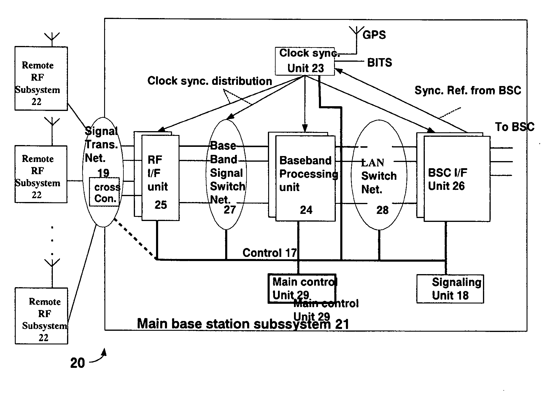
[0113]FIG. 3a is a block diagram showing the structure of centralized base station system 20 based on remote radio frequency units having an extensible architecture.

[0114]As shown in FIG. 3a, the base station system 20 comprising a main base station subsystem 21 and a plurality of remote radio frequency subsystems 22. The main base station subsystem 21 comprising a signal transmission network 19, a plurality of remote radio frequency interface units 25, a baseband signal flow switch network 27, a plurality of baseband processing units 24, a clock synchronization unit 23, a LAN (local area network) switch network 28, a base station controller interface unit 26, a main control unit 29 and a signaling unit 18. The main control unit 29 controls the other respective portions of the main base station subsystem 21 within the same shelf through a channel 17 (as shown with thick solid line), and the channel 17 may be implemented physically through LAN network or internal bus (such as PCI bus...


PUM


Abstract

A centralized base station system based on ATCA, comprising a main base station subsystem and one or more remote radio frequency subsystems, the main base station subsystem comprising: one or more shelves based on ATCA platform, each shelf comprising at least one control switch module of ATCA board form; one or more base station controller interface module; a signaling module; one or more baseband processing modules; one or more remote radio frequency interface modules; a first switch network comprising first switch network shelf back board BASE interface link, a control switch module and a first network switch unit; a second switch network comprising a shelf back board FABRIC interface link, a control switch module and a second network switch unit; a clock synchronization network comprising a shelf back board clock synchronization bus, a control switch module and a clock unit; and a signal transmission network, wherein the second network switch unit and the clock unit are further connected to the first network switch unit, one of the control switch modules of all the shelves is the main control module.

Description

TECHNICAL FIELD[0001]The present invention relates to a base station technique in a mobile communication system, in particular relates to a centralized base station architecture with radio frequency units being separated and its implementation on the ATCA (advanced telecommunication computer architecture) platform.BACKGROUND ART[0002]1. The Technique Based on Remote Radio Frequency Units and the Centralized Base Station[0003]In a mobile communication system, as shown in FIG. 1a, a wireless access network is typically composed of base stations (BTS) and a base station controller (BSC) or wireless networks controller (RNC) for controlling the base stations. As shown in FIG. 1b, a base station is mainly composed by a baseband processing subsystem, a radio frequency (RF) subsystem, antennas and etc., and performs transmission, reception and processing of wireless signals, and the base station may cover different cells through a plurality of antennas.[0004]In the mobile communication sys...

Claims


Application Information

Patent Timeline
Patent Type & Authority Applications(United States)
IPC IPC(8): H04M1/00H04W88/08
CPCH04W88/085
Inventor LIU, SHENGRUAN, SHAOYUNZHAO, BAIJUN
Owner UTSTARCOM TELECOM CO LTD
Why Eureka
Try Eureka