Rolled Copper or Copper Alloy Foil with Roughened Surface and Method of Roughening Rolled Copper or Copper Alloy Foil

a technology of rolled copper or copper alloy foil and surface roughening, which is applied in the direction of chemistry apparatus and processes, cores/yokes, transportation and packaging, etc., can solve the problems of significant deterioration in the etching properties of copper foil, difficult etching at a high aspect ratio, and undercutting during the etching process, so as to reduce craters, improve the effect of characteristics, and reduce the effect of crater siz

Active Publication Date: 2009-06-25
JX NIPPON MINING& METALS CORP
View PDF17 Cites 30 Cited by
  • Summary
  • Abstract
  • Description
  • Claims
  • Application Information

AI Technical Summary

Benefits of technology

[0026]As described above, the primary objective of the roughening method of a rolled copper or copper alloy foil is to inhibit the formation of craters, and the present invention enables to achieve the foregoing objective. The copper foil of the present invention subject to roughening treatment significantly affects the improvement in characteristics such as the adhesive strength with the resin layer, the acid resistance or anti-tin plating solution properties, the peel strength, etching unevenness and the gloss level. Further, the present invention is quite useful in achieving a fine wiring pattern.
[0027

Problems solved by technology

Conventionally used was an electrolytic copper foil subject to roughening treatment in order to improve the adhesive properties with resin, but there were problems in that the roughening treatment caused the significant deterioration in the etching properties of the copper foil, made etching difficult at a high aspect ratio, caused undercuts during the etching process, and made the bearing of a sufficiently fine pattern impossible.
Nevertheless, achieving a low profile of the electrolytic copper foil will cause a problem of deteriorating the adhesive strength between the electrolytic copper foil and the insulating polyimide layer.
Thus, there are demands of achieving a high-level fine wiring pattern on the one hand, however, there is a problem in that it is not possible to maintain the desired adhesive strength on the other hand, and the wiring

Method used


Image

  • Rolled Copper or Copper Alloy Foil with Roughened Surface and Method of Roughening Rolled Copper or Copper Alloy Foil
  • Rolled Copper or Copper Alloy Foil with Roughened Surface and Method of Roughening Rolled Copper or Copper Alloy Foil
  • Rolled Copper or Copper Alloy Foil with Roughened Surface and Method of Roughening Rolled Copper or Copper Alloy Foil

Examples


examples

[0077]Examples of the present invention are now explained. These Examples merely illustrate a preferred example, and the present invention shall in no way be limited thereby. In other words, all modifications, other embodiments and modes covered by the technical spirit of the present invention shall be included in this invention. Incidentally, the Comparative Examples are indicated in the latter part for comparison with the present invention.

example 4

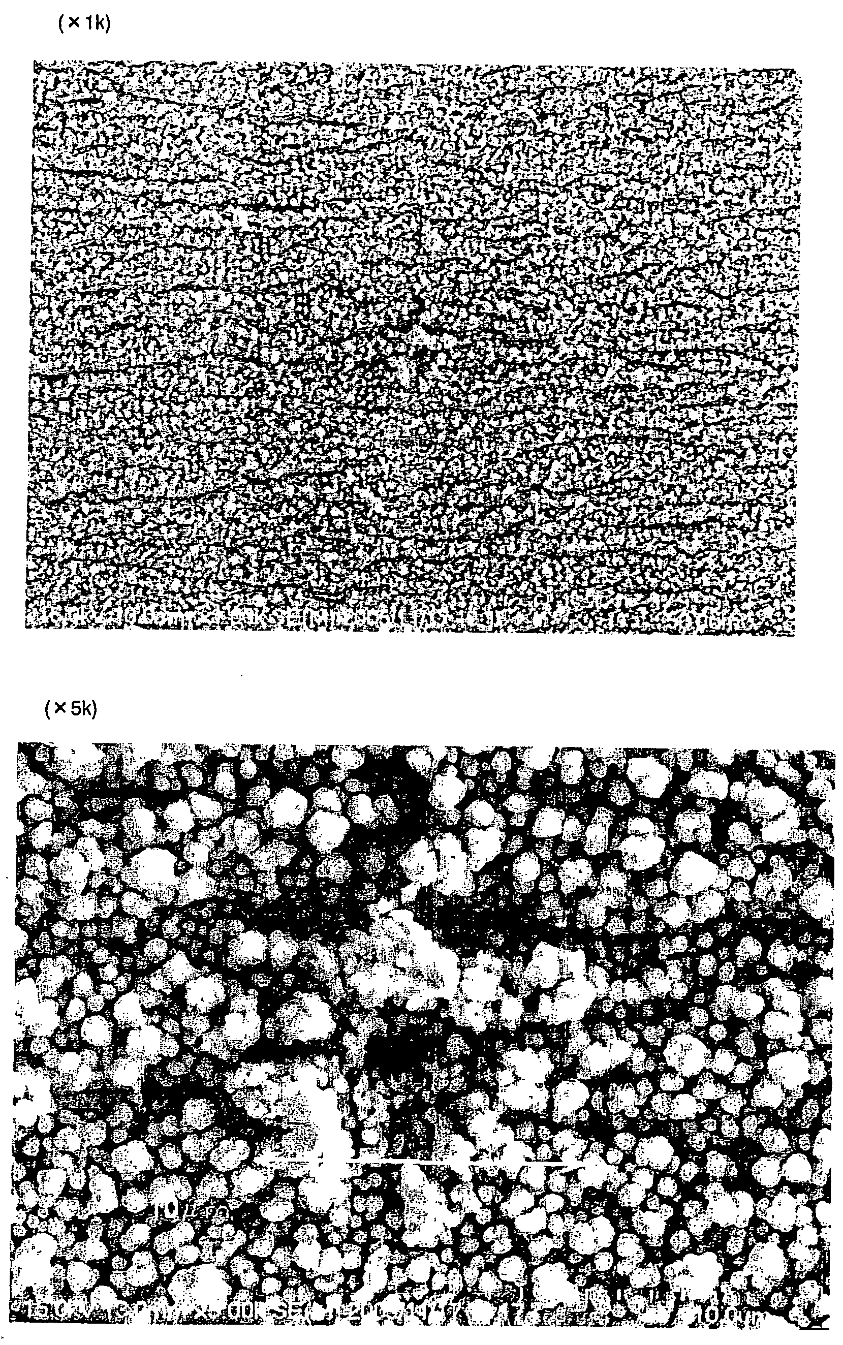
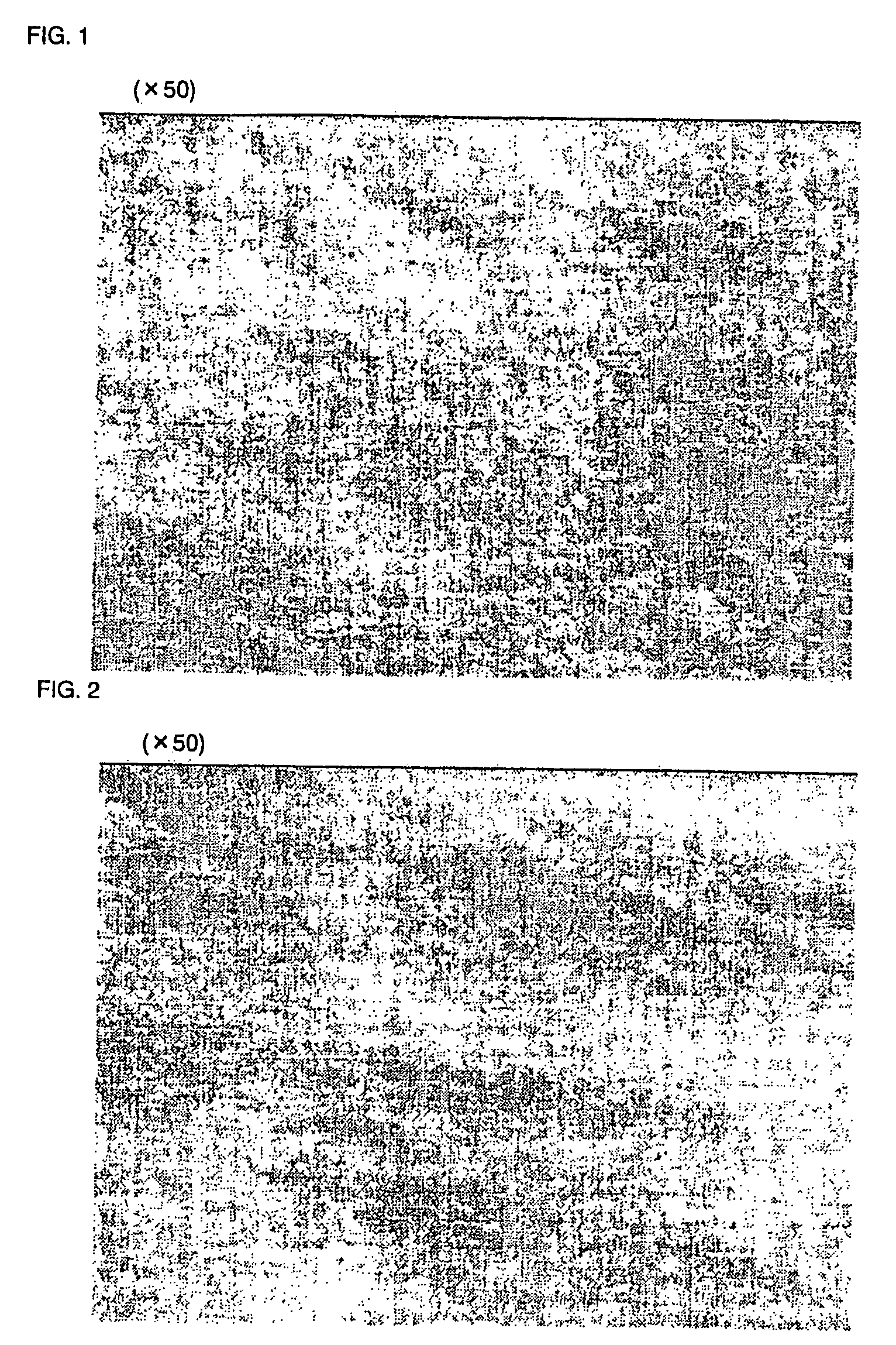
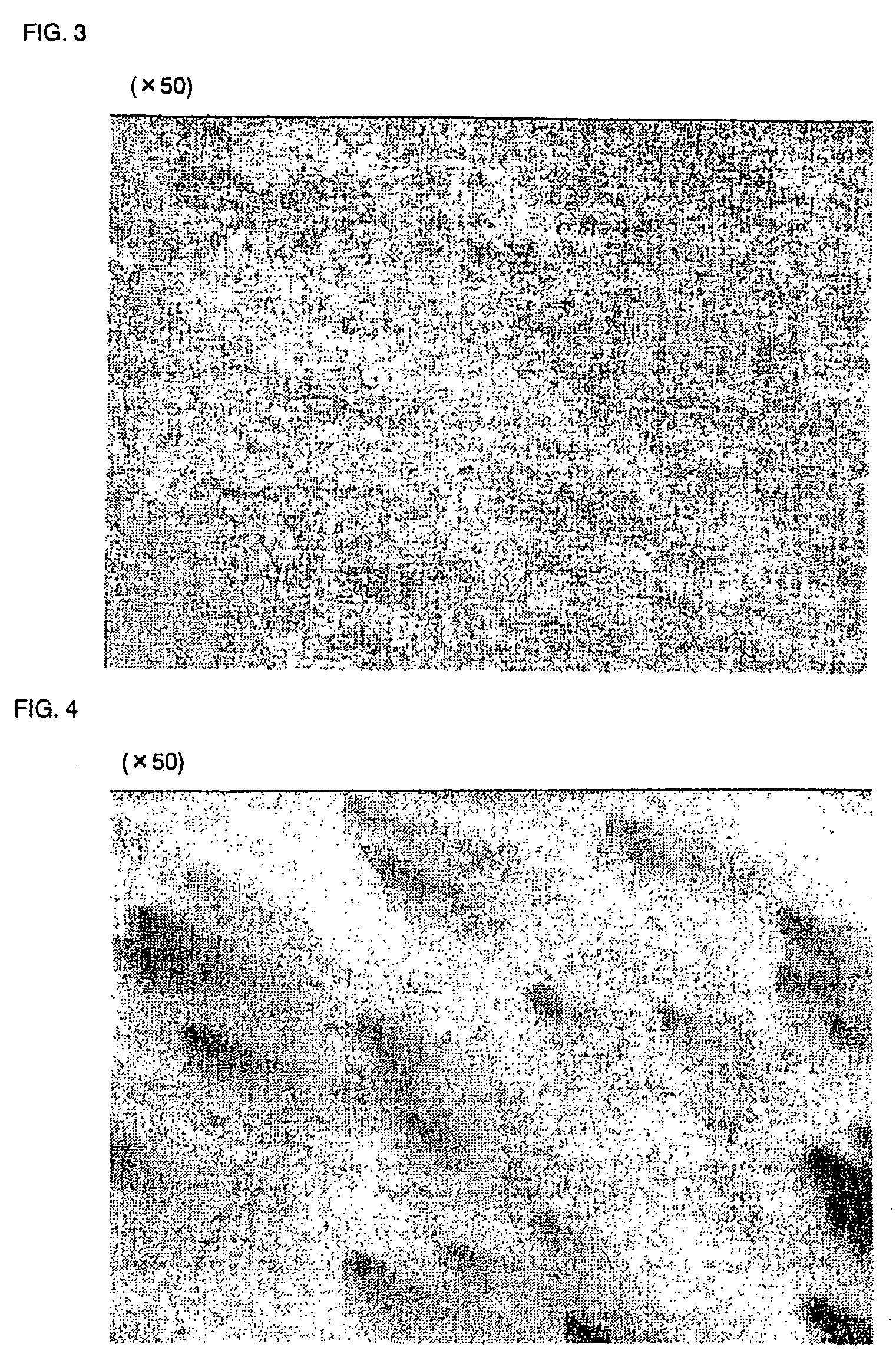
[0108]Next, the rolled copper foil subject to base plate as with Examples 1 to 3 above was subject to roughening treatment by way of copper plating treatment using plating baths additionally containing nickel sulfate (Example 4) or phosphorous acid (Example 5).

[0109]The foregoing conditions were used as the copper roughening plating bath and roughened copper plating conditions, that is, in the copper-nickel alloy plating treatment, 15 g / L of Cu ion concentration, 2 g / L of Ni ion concentration, 50 g / L of sulfuric acid, electrolytic solution temperature of 25° C., and current density of 50 A / dm2. The plating thickness was roughly 5000 μg / dm2.

[0110]As the additive, sodium dodecyl sulfate was used by 20 wtppm. Consequently, the crater count was the same as Example 1 at 0.14 craters / mm2. As evident from the foregoing explanation, the roughening plating of Example 4 also yielded the same result of reducing craters as with Examples 1 to 3.

example 5

Copper-Nickel-Phosphorous Alloy Plating Treatment

[0111]Copper-nickel-phosphorous alloy plating treatment was performed under the conditions of 15 g / L of Cu ion concentration, 2 g / L of Ni ion concentration, 1 g / L of P ion concentration, 50 g / L of sulfuric acid, electrolytic solution temperature of 25° C., and current density of 50 A / dm2. The plating thickness was roughly 50000 μg / dm2. As the additive, sodium dodecyl sulfate was used by 20 wtppm.

[0112]Consequently, the crater count was the same as Example 1 at 0.14 craters / mm2. As evident from the foregoing explanation, the roughening plating of Example 5 also yielded the same result of reducing craters as with Examples 1 to 3.


PUM

PropertyMeasurementUnit
Temperatureaaaaaaaaaa
Densityaaaaaaaaaa
Densityaaaaaaaaaa

Abstract

Provided is a rolled copper or copper alloy foil having a roughened surface formed of fine copper particles, obtained by subjecting a rolled copper or copper alloy foil to roughening plating with a plating bath containing copper sulfate (Cu equivalent of 1 to 50 g/L), 1 to 150 g/L of sulfuric acid, and one or more additives selected among sodium octyl sulfate, sodium decyl sulfate, and sodium dodecyl sulfate under the conditions of a temperature of 20 to 50° C. and a current density of 10 to 100 A/dm2. The provided rolled copper or copper alloy foil subject to roughening is reduced in craters which are obvious defects unique to rolled copper or copper alloy foils having a roughened surface, has high strength, adhesive strength with the resin layer, acid resistance and anti-tin plating solution properties, high peel strength, favorable etching properties and gloss level, and also suits for use in producing a flexible printed wiring board capable of bearing a fine wiring pattern. Additionally provided is a method of roughening the rolled copper or copper alloy foil.

Description

TECHNICAL FIELD[0001]The present invention generally relates to a rolled copper or copper alloy foil comprising a roughened surface, and in particular relates to a rolled copper or copper alloy foil which has reduced craters, high strength, adhesive strength with the resin layer, acid resistance and anti-tin plating solution properties, high peel strength, favorable etching properties and gloss level, and is also suitable for use in producing a flexible printed wiring board capable of bearing a fine wiring pattern, as well as to a method of roughening the rolled copper or copper alloy foil. Incidentally, the term “craters” as used herein refers to the minute spot-shaped surface irregularities caused by uneven roughening treatment. In addition, the expressions of % and ppm used herein refer to wt % and wtppm, respectively.[0002]Since a high purity copper foil is soft in comparison to copper alloy, there is an advantage in that rolling can be performed easily and it is possible to pro...

Claims


Application Information

Patent Timeline
IPC IPC(8): B32B15/02C22C9/00C25D7/00C25D5/00
CPCC22C9/06Y10T428/12063C25D5/10C25D7/0614C25D7/0692H05K3/384H05K2201/0355H05K2203/0307H05K2203/0723C22C9/00C22C9/02C22C9/04Y10T428/12181Y10T428/12993Y10T428/12014Y10T428/1291Y10T428/12903Y10T428/12438Y10T428/12431C25D3/38C25D5/605
Inventor KOBAYASHI, YOUSUKEMIKI, ATSUSHIYAMANISHI, KEISUKE
Owner JX NIPPON MINING& METALS CORP
Why Eureka
Try Eureka