Nitrogen inerting system for explosion prevention in aircraft fuel tank & oxygenating system for improving combustion efficiency of aerospace rockets/ aircraft engines

a technology of aircraft fuel tank and oxygenating system, which is applied in the direction of liquid degasification, separation processes, transportation and packaging, etc., can solve the problems of global warming, sacrificing the airplane's overall system design improvement, increasing the overall cost of manufacture, reliability and operation of such inerting systems, etc., to achieve high speed and increase rotational speed

Inactive Publication Date: 2009-07-02
BOSE RANENDRA K
View PDF29 Cites 24 Cited by
  • Summary
  • Abstract
  • Description
  • Claims
  • Application Information

AI Technical Summary

Benefits of technology

[0011]Where as, the comparatively in-expensive, light-weight Bose System's Improved centrifugal gas separation technology could be used simply, by tapping the Aircraft engine's compressed air line to the Air Conditioning System, or alternatively, using an Auxiliary, electrically-operated Air Compressor, in order to drive the free-wheeling gas turbine at a very high speed. Thus, the expanding compressed air exiting from the gas turbine blades, creates a high-speed, convoluting gas mass which further in...

Problems solved by technology

However, these Systems have been now discarded because the release of used-up halogens results in ozone depletion in the atmosphere, causing Global Warming.
Thus, the prior art inerting systems are complicated, energy-intensive and have drawbacks, including costly operational components, that require large space and weight ...

Method used


Image

  • Nitrogen inerting system for explosion prevention in aircraft fuel tank & oxygenating system for improving combustion efficiency of aerospace rockets/ aircraft engines
  • Nitrogen inerting system for explosion prevention in aircraft fuel tank & oxygenating system for improving combustion efficiency of aerospace rockets/ aircraft engines
  • Nitrogen inerting system for explosion prevention in aircraft fuel tank & oxygenating system for improving combustion efficiency of aerospace rockets/ aircraft engines

Examples


Embodiment Construction

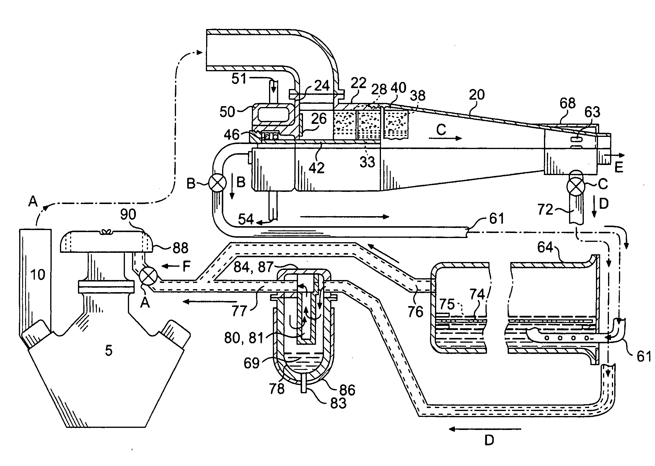
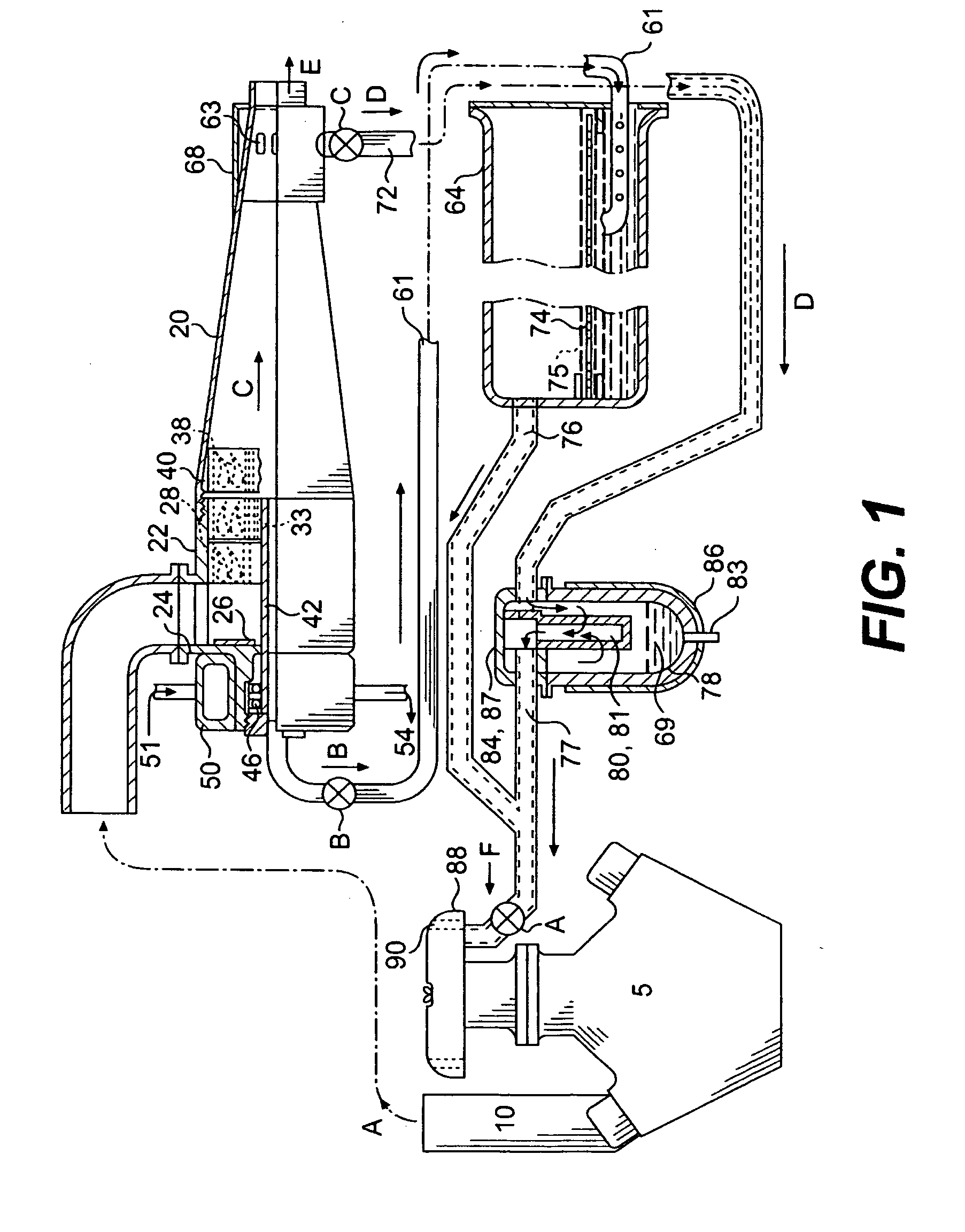
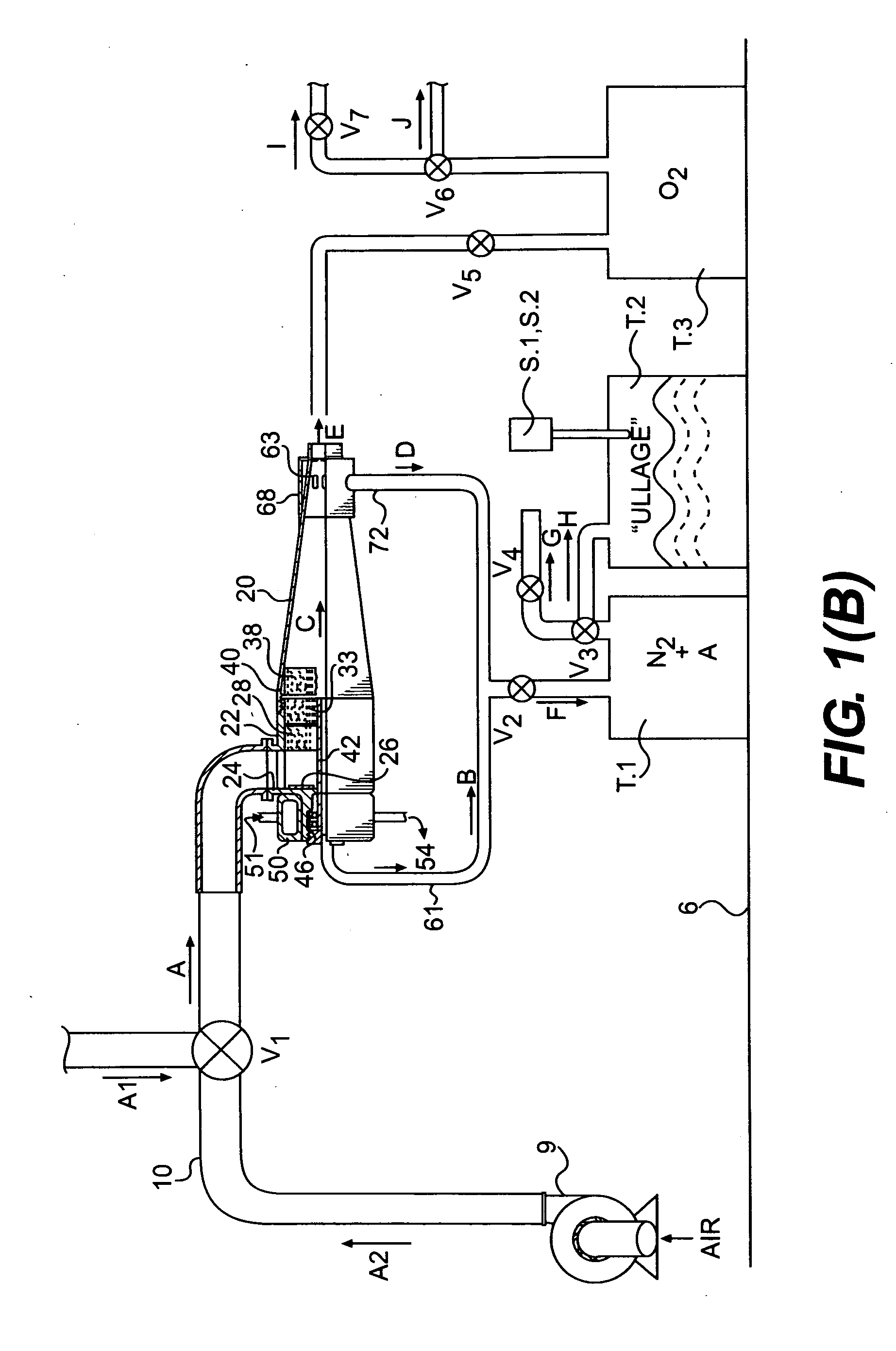
[0027]The present invention of a Nitrogen Inerting System that may be used on airplane's and other hydrocarbon fuel tanks and similar Applications required in Anaerobic Digesters in the biomass gas recovery and other processes, or similar Oxygenating Applications as required in Coal-Power Plants, Steel Plant Blast Furnaces for energy efficiency, NOx gas prevention, CO2 recovery from their exhaust & other industrial processes, is illustrated in FIG. 1.(B) of the drawings. The alphabetical reference characters A-J designate the gases / gas mixtures as follows:

ArrowGasesA:Compressed Air from Airplane air conditioning intake line (A1) or Auxiliary AirCompressor (A2) feeds to rotate the turbine impeller at very high speedB:Lighter inner core of gases comprising primarily inert gas: nitrogen, are fed intothe Inert gas tank for storageC:Heavier of the heavy outer layer of gas mixture of non-combustible gases, such as,Argon, and the lighter of the heavier and combustible gases, such as, oxyge...


PUM

PropertyMeasurementUnit
Pressureaaaaaaaaaa
Angleaaaaaaaaaa
Fractionaaaaaaaaaa

Abstract

Compressed Air from an aircraft rocket engine's compressed air line to its air-conditioning system, or an Auxiliary Air Compressor out-put is used, for energizing a high-speed gas turbine. The very high-speed convoluting air discharge into a vortex cone causes a first separation of the Air gas components, by stratifying into heavier (Argon), medium (Oxygen) and lighter (Nitrogen) components, where in the heavier and lighter components are non-combustible, inert gases and the medium is a combustible gas. The lighter non-combustible component (Nitrogen) exits from the turbine in one direction for storage in the Inert gas tank. The heavier (Argon) and medium (Oxygen) components together move in the opposite direction for having a second stratifying separation downstream in the vortex tube, to separate non-combustible, heavier (Argon) gas from combustible medium (Oxygen) gas components. The combustible, medium (Oxygen) component exits the vortex tube open end, to flow into an Oxygenating storage tank; whereas, the heavier, non-combustible(Argon) gas is piped into the Inert gas storage tank. Both gas storage tank in-flow lines are fitted with non-return valves. The out flow lines from the Inert tank to either Fuel Tank “Ullage” or “OBGIS” areas are fitted with electronic control valves, operated by signals received from fibre-optic Temperature/Pressure/Oxygen concentration Sensors in the Fuel tank “Ullage” or “OBGIS: areas. Likewise, the outflow lines from the Oxygenating tank are fitted with electronc control valves activated by engine “takeoff” or Passenger cabin low oxygen signals, respectively.

Description

CROSS-REFERENCES TO RELATED APPLICATIONS[0001]This Invention is an improvement over the system shown in my prior U.S. Pat. No. 6,398,851B1 issued Jun. 4, 2002; U.S. Pat. No. 4,399,107 issued Aug. 16, 1983; 4,235,845 issued Nov. 25, 1980; U.S. Pat. No. 3,892,070 issued Jul. 1, 1975; U.S. Pat. No. 3,861,142 issued Jan. 21, 1975 and Canadian Patent Nos: 1,104,060 issued Jun. 30, 1981; 1,030,777 issued May 5, 1978. All USA and Canadian patents are incorporated by reference herein, the present disclosures being based primarily on these, which are repeated herein.FEDERALLY SPONSORED RELIABILITY AND LIFECYCLE TESTS[0002]My patented, “Anti-Pollution System For Automobiles”, Experimental Prototype herein after referred to as the Bose System, was based on U.S. Pat. Nos. 4,235,845; 3,892,070 and 3,861,142. This System received an US D.O.E Grant Award from its Office of Energy Related Inventions. The Grant was used to demonstrate the Bose System's pollutant gas separation and emission control e...

Claims


Application Information

Patent Timeline
IPC IPC(8): B65D90/22
CPCB01D53/24B01D2256/12B01D2256/10
Inventor BOSE, RANENDRA K.
Owner BOSE RANENDRA K
Why Eureka
Try Eureka