
Ceramic interconnect for fuel cell stacks

Inactive Publication Date: 2009-07-02
SAINT GOBAIN CERAMICS & PLASTICS INC
View PDF7 Cites 31 Cited by
  • Summary
  • Abstract
  • Description
  • Claims
  • Application Information

AI Technical Summary

Benefits of technology

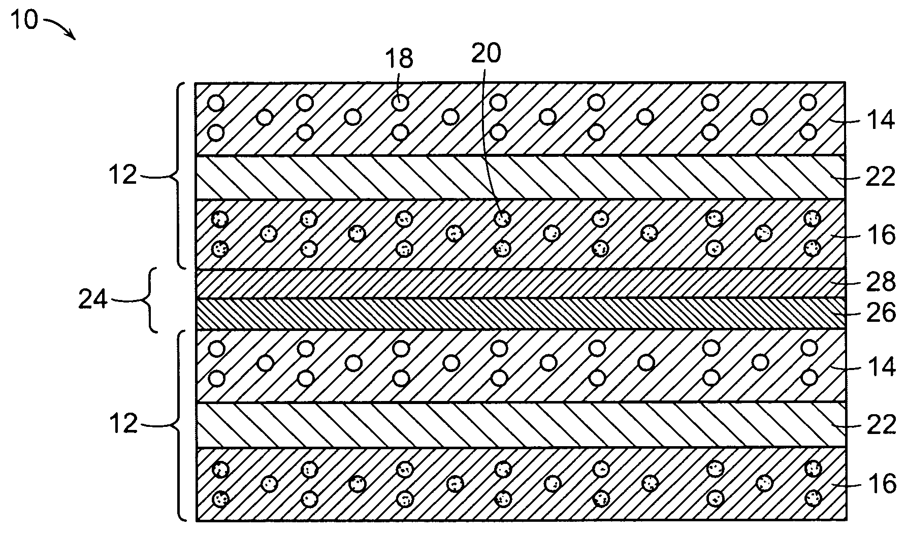
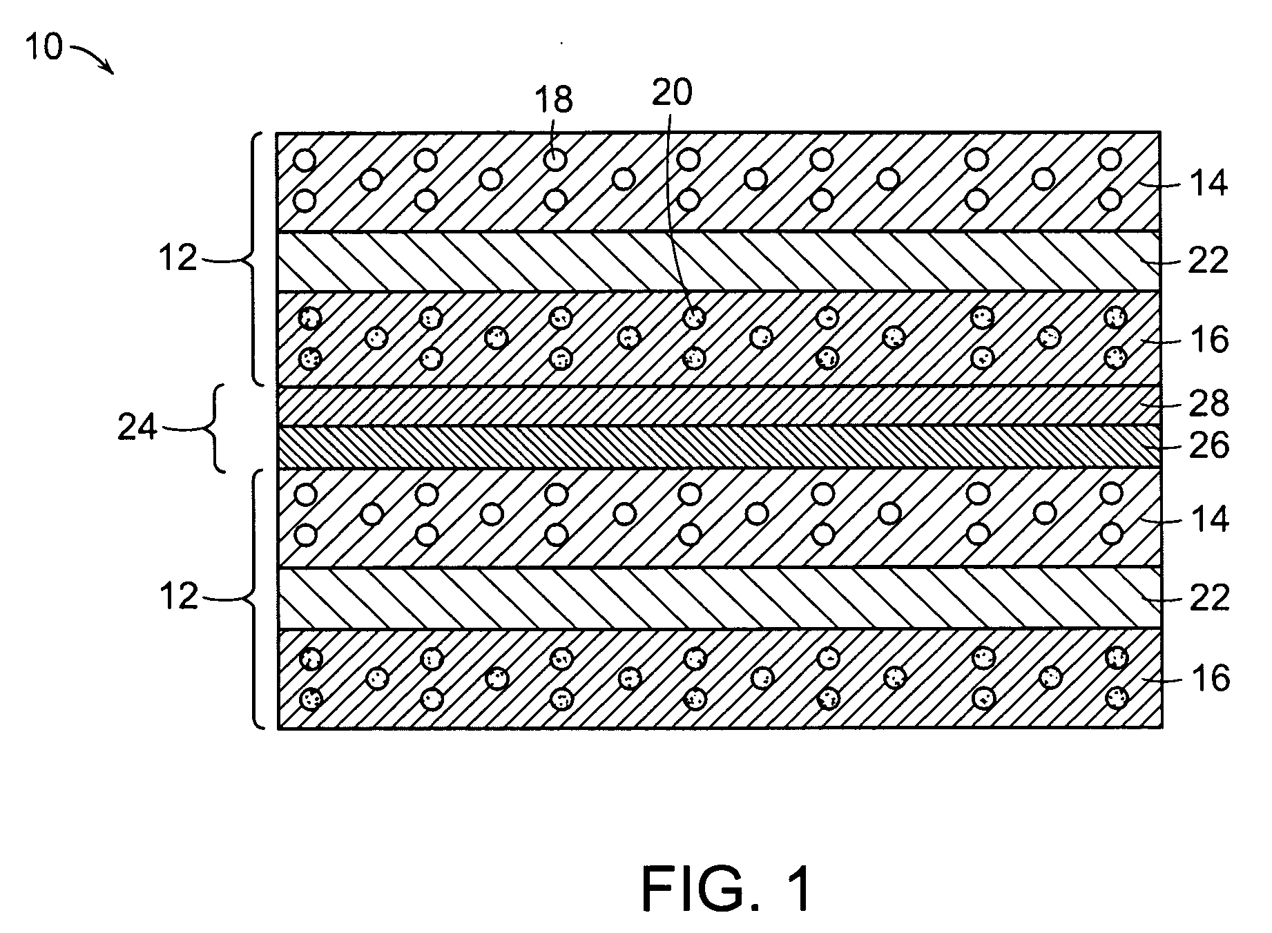
[0006]In the invention, the first layer of (La,Mn)Sr-titanate based perovskite, which is in contact with the first electrode exposed to an oxygen source, can provide relatively high sinterability (e.g., sinterability to over 95% of theoretical density at a temperature lower than about 1,500° C.), stability in the oxidizing atmosphere and / or electrical conductivity. The second layer of (Nb,Y)Sr-titanate based perovskite and / or (La)Sr-titanate based perovskite, which is in contact with the second electrode exposed to a fuel source, can provide high electrical conductivity and stability in the reducing atmosphere. The (La,Mn)Sr-titanate based perovskite and the (Nb,Y)Sr-titanate based perovskite materials have similar thermal expansion coefficients with each other. For example, La0.4Sr0.6Ti0.4Mn0.6O3 has an average thermal expansion coefficient of 11.9×10⁻⁶ K−1 at 30° C.-1,000° C. in air, and Sr0.86Y0.08TiO3 has an average thermal expansion coefficient of 11-12×10−6 K−1 at 25° C.-1,000° C. in air. Thus, both of the first layer of (La,Mn)Sr-titanate based perovskite and the second layer of (Nb,Y)Sr-titanate based perovskite can be co-sintered at the same time, minimizing process steps.
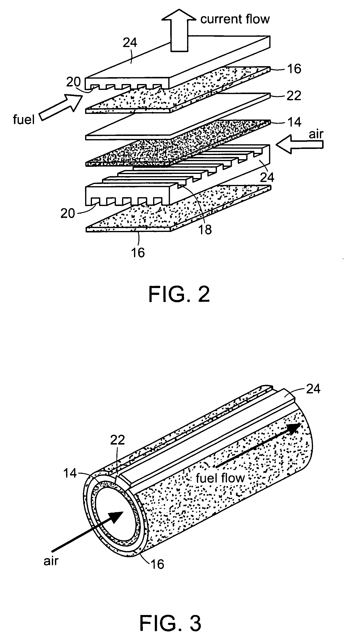
[0009]This invention has many advantages. Bi-layer ceramic interconnects of the invention meet all the major requirements for solid oxide fuel cell (SOFC) stack interconnects. (La,Mn)Sr-titanate based perovskite is stable and its electrical conductivity is high in an oxidizing atmosphere, and therefore this material can be used on the air side in the bi-layer ceramic interconnect. (Nb,Y)Sr-titanate based perovskite and (La)Sr-titanate based perovskite is stable and its electrical conductivity is high in a reducing atmosphere, and therefore this material can be used on the fuel side in the bi-layer ceramic interconnect. These materials also have the advantage that, containing no chromium, they do not have the problems associated with lanthanum chromites (LaCrO3). The present invention can be used in a solid oxide fuel cell (SOFC) system, particularly in planar SOFC stacks. SOFCs offer the potential of high efficiency electricity generation, with low emissions and low noise operation. They are also seen as offering a favorable combination of electrical efficiency, co-generation efficiency and fuel processing simplicity. One example of a use for SOFCs is in a home or other building. The SOFC can use the same fuel as used to heat the home, such as natural gas. The SOFC system can run for extended periods of time to generate electricity to power the home and if excess amounts are generated, the excess can be sold to the electric grid. Also, the heat generated in the SOFC system can be used to provide hot water for the home. SOFCs can be particularly useful in areas where electric service is unreliable or non-existent.

Problems solved by technology

Interconnects are one of the critical issues limiting commercialization of solid oxide fuel cells.
While metal interconnects are relatively easy to fabricate and process, they generally suffer from high power degradation rates (e.g. 10% / 1,000 h) partly due to formation of metal oxides, such as Cr2O3, at an interconnect-anode / cathode interface during operation.
However, lanthanum chromites generally are difficult to fully densify and require high temperatures, such as at or above about 1,600° C., for sintering.
Although certain doped lanthanum chromites, such as strontium-doped and calcium-doped lanthanum chromites, can be sintered at lower temperatures, they tend to be either unstable or reactive with an electrolyte (e.g., a zirconia electrolyte) and / or an anode.

Method used


Image

  • Ceramic interconnect for fuel cell stacks
  • Ceramic interconnect for fuel cell stacks
  • Ceramic interconnect for fuel cell stacks

Examples


example

Bi-layer Interconnect of La0.4Sr0.6Ti0.4Mn0.6O3−δ (“LSTM”) and Sr0.86Y0.08TiO3−δ (“YST”)

[0045]A small amount of (La,Mn)Sr-titanate, La0.4Sr0.6Ti0.4Mn0.6O3−δ (LSTM), powder (2.0 grams) was added on the top of (Nb,Y)Sr-titanate, Sr0.86Y0.08TiO3−δ (YST), powder (1.0 gram). The LSTM / YST powders were die-pressed together using a steel die with a diameter of 1.125 inches at a load of 10,000 lbs. The La0.4Sr0.6Ti0.4Mn0.6O3−δ powder was binderized before die-pressing with 0.5 wt % polyethylene glycol (PEG-400) and 0.7 wt % polyvinyl alcohol (PVA 21205) in order to increase the strength of the green body for handling. The die-pressed LSTM / YST powders with a bi-layer structure were then co-sintered pressurelessly at 1350° C. for one hour in air. The LSTM / YST bi-layer structure was cross sectioned, mounted in an epoxy, and polished for SEM (scanning electron microscope) examination. FIG. 4 shows an SEM result of the fabricated LSTM / YST bi-layer structure. As shown in FIG. 4, both LSTM and YST ...


PUM

PropertyMeasurementUnit
Lengthaaaaaaaaaa
Lengthaaaaaaaaaa
Thicknessaaaaaaaaaa

Abstract

A fuel cell comprises a plurality of sub-cells, each sub-cell including a first electrode in fluid communication with a source of oxygen gas, a second electrode in fluid communication with a source of a fuel gas, and a solid electrolyte between the first electrode and the second electrode. The sub-cells are connected with each other with an interconnect. The interconnect includes a first layer in contact with the first electrode of each cell, and a second layer in contact with the second electrode of each cell. The first layer includes a (La,Mn)Sr-titanate based perovskite represented by the empirical formula of LaySr(1−y)Ti(1−x)MnxOb. In one embodiment, the second layer includes a (Nb,Y)Sr-titanate perovskite represented by the empirical formula of Sr(1−1.5z−0.5k±δ)YzNbkTi(1−k)Od. In another embodiment, the interconnect has a thickness of between about 10 μm and about 100 μm, and the second layer of the interconnect includes a (La)Sr-titanate based perovskite represented by the empirical formula of Sr(1−z±δ)LazTiOd.

Description

RELATED APPLICATIONS[0001]This application claims the benefit of U.S. Provisional Application No. 61 / 063,643, filed on Feb. 5, 2008 and U.S. Provisional Application No. 61 / 009,003, filed on Dec. 21, 2007. The entire teachings of the above applications are incorporated herein by reference.BACKGROUND OF THE INVENTION[0002]A fuel cell is a device that generates electricity by a chemical reaction. Among various fuel cells, solid oxide fuel cells use a hard, ceramic compound of metal (e.g., calcium or zirconium) oxide as an electrolyte. Typically, in the solid oxide fuel cells, an oxygen gas, such as O2, is reduced to oxygen ions (O2−) at the cathode, and a fuel gas, such as hydrogen gas (H2) gas, is oxidized with the oxygen ions to form water at the anode.[0003]Interconnects are one of the critical issues limiting commercialization of solid oxide fuel cells. Currently, most companies and researchers working with planar cells are using coated metal interconnects. While metal interconnect...

Claims


Application Information

Patent Timeline
IPC IPC(8): H01M8/10B05D5/12H01M6/00
CPCC04B35/016Y10T29/49108C04B35/2641C04B35/47C04B2235/3213C04B2235/3225C04B2235/3227C04B2235/3232C04B2235/3251C04B2235/3262C04B2235/3275C04B2235/768H01M8/0215H01M8/0228H01M8/1226H01M8/2435H01M2008/1293Y02E60/521Y02E60/525H01M8/0217C04B35/2633Y02E60/50H01M8/243H01M8/2432H01M8/2404
Inventor LIN, GUANGYONG
Owner SAINT GOBAIN CERAMICS & PLASTICS INC
Learn More