Single-Walled Carbon Nanotubes, Carbon Fiber Aggregate Containing the Single-Walled Carbon Nanotubes, and Method for Producing Those

a single-walled carbon nanotube and carbon fiber technology, applied in the field of single-walled carbon nanotubes, carbon fiber aggregates containing the same, and a method for producing those, can solve the problems of high cost, difficult to precisely control a diameter range of less than, and inability to obtain single-walled carbon nanotubes with such uniformity and high purity, and achieve high purity, high quality, and high strength.

Inactive Publication Date: 2009-07-23
NAT INST OF ADVANCED IND SCI & TECH
View PDF4 Cites 34 Cited by
  • Summary
  • Abstract
  • Description
  • Claims
  • Application Information

AI Technical Summary

Benefits of technology

[0027]The single-walled carbon nanotube according to the present invention has a diameter in a range of from 1.0 to 2.0 nm, an intensity ratio IG / ID between G-band and D-band in a Raman spectrum of 200 or more, and extremely high purity and high quality. Therefore, semiconducting, mechanical and optical characteristics become homogeneous.
[0028]Therefore, for example, a wire rod obtained by spinning the uniform single-walled carbon nanotube has the structure that single-walled carbon nanotubes are densely packed in the inside of the wire rod, and are strongly bonded by a van der Waals' force, respectively. As a result, this gives a wire rod having very high strength as compared with a wire rod obtained by spinning single-walled carbon nanotubes having heterogeneous diameter distribution or carbon nanotubes having a large diameter. This fact brings about great industrial contribution in, for example, electronics field or high-strength carbon material field.
[0029]Furthermore, according to the method for producing a single-walled carbon nanotube or a carbon fiber aggregate containing the same, a single-walled carbon nanotube having a controlled diameter, particularly a high purity single-walled carbon nanotube having a diameter in a range of from 1.0 to 2.0 nm, and a carbon fiber aggregate containing the same can be produced efficiently, in large amount and inexpensively.

Problems solved by technology

However, it is difficult to precisely control a diameter in a range of less than this from the point of preparation of metal ultrafine particles which become a catalyst.
A single-walled carbon nanotube having a diameter range provided with such uniformity and high purity could not be obtained by the conventional methods.
Thus, a single-walled carbon nanotube having high purity and uniform diameter useful as an industrial material involves high cost from the difficulty in production standpoint, and is almost not used in high-strength carbon wire rod which is one of the main uses as a carbon fiber.
However, the multi-walled carbon nanotube has a large diameter of 5 nm or more and is heterogeneous.
Therefore, strength of a wire rod obtained is merely about 460 MPa, and such a wire rod could not be put into practical use.

Method used


Image

  • Single-Walled Carbon Nanotubes, Carbon Fiber Aggregate Containing the Single-Walled Carbon Nanotubes, and Method for Producing Those
  • Single-Walled Carbon Nanotubes, Carbon Fiber Aggregate Containing the Single-Walled Carbon Nanotubes, and Method for Producing Those
  • Single-Walled Carbon Nanotubes, Carbon Fiber Aggregate Containing the Single-Walled Carbon Nanotubes, and Method for Producing Those

Examples


example 1

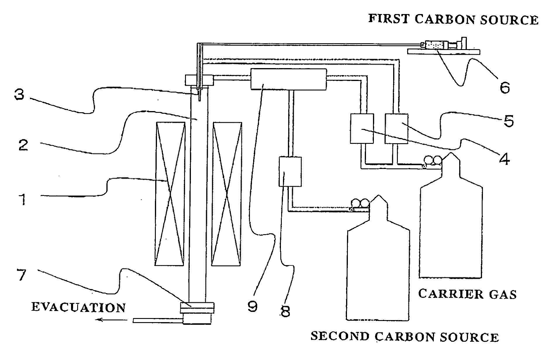
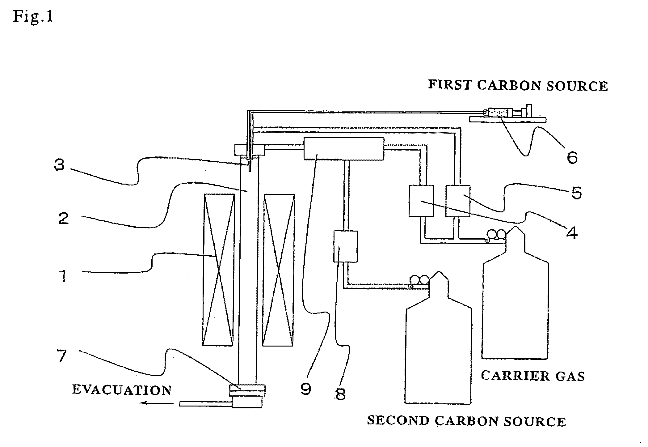
[0079]A single-walled carbon nanotube of the present invention was produced using a vertical single-walled carbon nanotube production apparatus as shown in FIG. 1.

[0080]The apparatus is constituted of a 4 kW electric furnace 1, a mullite reaction tube 2 having an inner diameter of 5.0 cm and an outer diameter of 5.5 cm, a spray nozzle 3, a mass flow controller of first carrier gas 4, a mass flow controller of second carrier gas 5, a microfeeder 6, a recovery filter 7, a mass flow controller of second carbon source 8 and a gas mixer column 9.

[0081]A raw material liquid having a mixing ratio of decalin as a first carbon source:ferrocene as an organic transition metal compound:thiophene as an organic sulfur compound of 100:4:2 in weight ratio was stored in the microfeeder 6. On the other hand, ethylene was used as a second carbon source, and its flow rate was controlled through the second carbon flow meter 8 and the gas mixer 9.

[0082]Using hydrogen having a flow rate of 7 liters / min as...

example 2

[0085]Experiment was conducted in the same manner as in Example 1 except that the second carbon source flow rate was changed to 5.0 sccm and the reaction time was changed to 1 hour. The product thus obtained is used as Sample 2.

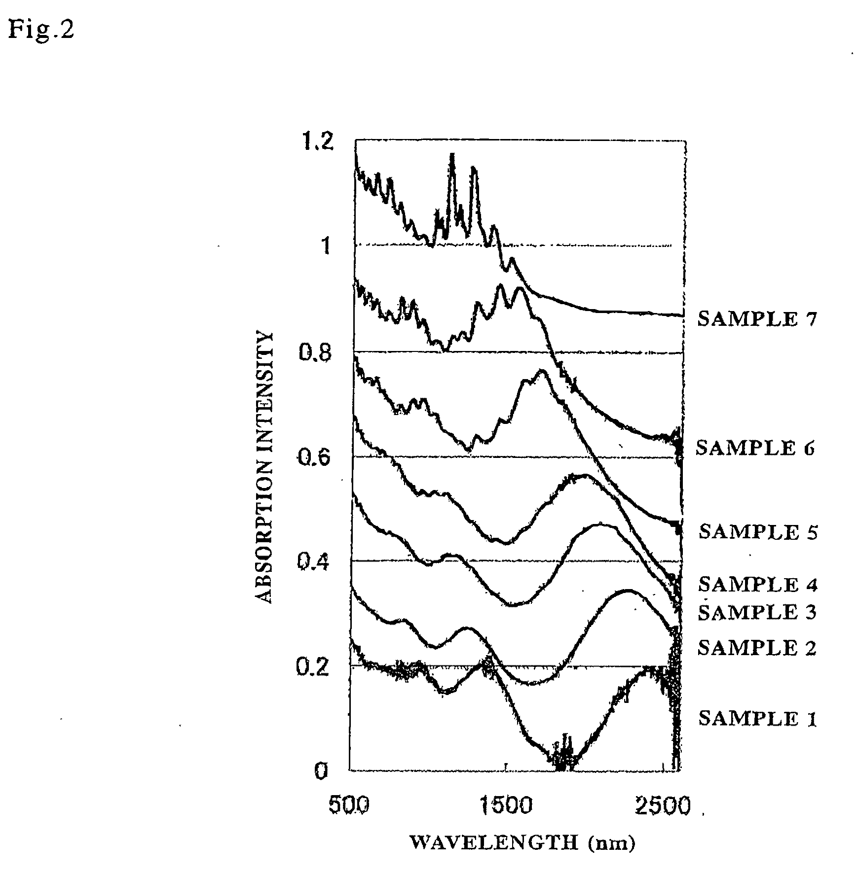
[0086]The yield was 19.5 mg. As a result of estimating a diameter distribution of a single-walled carbon nanotube in the same manner as in Example 1, peak at 2,285 nm was observed as shown in FIG. 2. This corresponds to that a diameter is 1.9 nm.

example 3

[0087]Experiment was conducted in the same manners as in Examples 1 and 2 except that the second carbon source flow rate was changed to 10.0 sccm. The product thus obtained is used as Sample 3.

[0088]The yield was 20.4 mg. As a result of estimating a diameter distribution of a single-walled carbon nanotube in the same manner as in Example 1, peak at 2,120 nm was observed as shown in FIG. 2. This corresponds to that a diameter is 1.7 nm.

[0089]It is seen from the results of Examples 2 and 3 that the diameter of the single-walled carbon nanotubes produced is 0.1 to 0.2 nm smaller than that of Example 1. This means that the diameter of a single-walled carbon nanotube can precisely be controlled with about 0.1 nm increments by appropriately controlling the second carbon source flow rate.


PUM

PropertyMeasurementUnit
diameteraaaaaaaaaa
diameteraaaaaaaaaa
diameteraaaaaaaaaa

Abstract

It relates to high purity single-walled carbon nanotubes having controlled diameter, useful as industrial materials, including high-strength carbon wire rods, particularly uniform single-walled carbon nanotubes having diameter fallen in a range of from 1.0 to 2.0 nm, and a method for producing the same efficiently, in large amount and inexpensively. The single-walled carbon nanotube obtained is characterized in that its diameter is fallen in a range of from 1.0 to 2.0 nm, and an intensity ratio IG/ID between G-band and D-band in a Raman spectrum is 200 or more. Furthermore, those single-walled carbon nanotubes are synthesized by a gas-phase flow CVD method that uses a saturated aliphatic hydrocarbon which is liquid at ordinary temperature as a first carbon source and an unsaturated aliphatic hydrocarbon which is gas at ordinary temperature as a second carbon source.

Description

TECHNICAL FIELD[0001]The present invention relates to a single-walled carbon nanotube, a carbon fiber aggregate containing the same, and a method for producing those. More particularly, it relates to a method for producing a carbon fiber aggregate containing a single-walled carbon nanotube having a specific controlled diameter from a carbon-containing source by a gas-phase flow CVD method in large amount and inexpensively.BACKGROUND ART[0002]Roughly classifying, three kinds of methods of an arc discharge method (see Patent Document 1), a laser vaporization method (see Non-Patent Document 1) and a chemical vapor deposition method (CVD method) (see Patent Document 2) are known as a method for synthesizing a single-walled carbon nanotubes.[0003]Of those, the CVD method is an effective method for synthesizing in large amount and inexpensively. Roughly classifying the CVD method, there are a substrate CVD method of producing by growing from a catalyst supported on substrates or support m...

Claims


Application Information

Patent Timeline
Patent Type & Authority Applications(United States)
IPC IPC(8): B32B1/00C09K3/00D01F9/12B82B1/00B82B3/00
CPCC01B2202/36D01F9/127D01F9/133B82Y30/00Y10T428/2982C01B31/0233C01B2202/02Y10T428/2918B82Y40/00C01B32/162B82B3/0009B82B3/0066C01B2202/30
Inventor SAITO, TAKESHIOHSHIMA, SATOSHIYUMURA, MOTOO
Owner NAT INST OF ADVANCED IND SCI & TECH
Why Eureka
Try Eureka