Zinc oxide ceramics and a manufacturing method for the same, a sputtering target

a technology of zinc oxide ceramics and manufacturing methods, applied in the direction of diaphragms, metallic material coating processes, electrical equipment, etc., can solve the problems of high cost of target, and influence of price on the manufacturing cost of liquid crystal displays or solar cells

Inactive Publication Date: 2009-08-06
HITACHI METALS LTD
View PDF0 Cites 58 Cited by
  • Summary
  • Abstract
  • Description
  • Claims
  • Application Information

AI Technical Summary

Benefits of technology

[0031]Moreover, in the manufacturing method for zinc oxide ceramics of the present invention, wherein, mixing molar ratio of sum of said 1st ZnO powder and said 3rd ZnO powder to sum of said 1st oxide powder and said 2nd oxide powder is 1 or more, and 200 or less, in said calcination powder production process.
[003...

Problems solved by technology

Furthermore, this target is very expensive generally and that price influences the manufacturing cost of the liquid crystal display or the solar cell greatly.
However, since indium(In) which is a main component of the target is expensive, the target becomes expensive.
Since area of the target for forming electrodes used for liquid crystal displays or solar cells with large area must be large as these, the cost of the target makes them expensive.
However, it was difficult actually to obtain the transparent electrodes made of BZO or AZO with low resistivity repeatedly using these targets, and the resistivity became higher than that of ITO.
Because, abnormal discharge arises frequently in the sputtering apparatus during the sputtering of these materials.
Then, the thin film was hard to be formed repeatedly since the abnormal discharge occurred frequently during the sputtering of BZO or AZO.
Problem in production of the ceramics of AZO is that the sintering of ZnO itself which is the main component is disturbed by Al2O3 doping.
Therefore, when the Al2O3 doping is heavy, densified ceramics were not obtained, and inhomegeneity causing the abnormal discharge arose.
By the way, conducting films (transparent electrodes) made of such zinc oxides has poor heat resistance and poor moisture resistance in the air generally.
However, the ceramics of BZO or AZ...

Method used


Image

  • Zinc oxide ceramics and a manufacturing method for the same, a sputtering target
  • Zinc oxide ceramics and a manufacturing method for the same, a sputtering target
  • Zinc oxide ceramics and a manufacturing method for the same, a sputtering target

Examples


1st embodiment

The 1st Embodiment

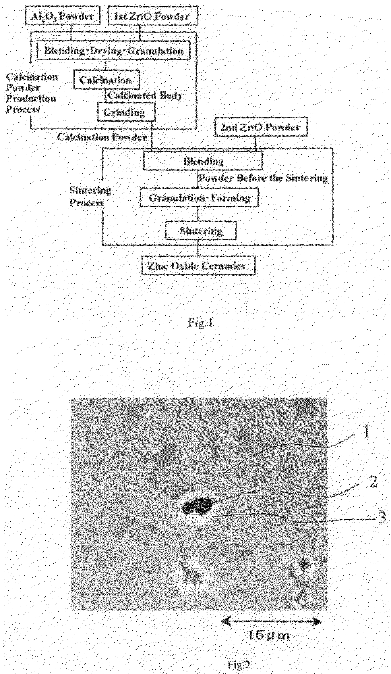
[0065]Manufacturing method for the zinc oxide ceramics concerning the 1st embodiment of this invention is a production method for the zinc oxide ceramics made of ZnO doped with Al2O3, or a manufacturing method for the zinc oxide ceramics made of ZnO doped with Ga2O3. This manufacturing method comprises, calcination powder production process in which 1st ZnO powder and Al2O3 etc., powder are blended and calcinated, and sintering process in which 2nd ZnO powder and calcination powder produced by the calcination powder production process are blended and molded into a molded body and the molded body is sintered.

[0066]In the manufacturing method for the zinc oxide ceramics concerning the 1st embodiment of this invention, Al2O3 or Ga2O3 is used as the oxide powder (dopant to the ceramics). Here, the ceramics are produced not by blending Al2O3 powder and ZnO powder, molding, and sintering the molded body into the ceramics, instead, the ceramics is produced by producing at...

2nd embodiment

The 2nd Embodiment

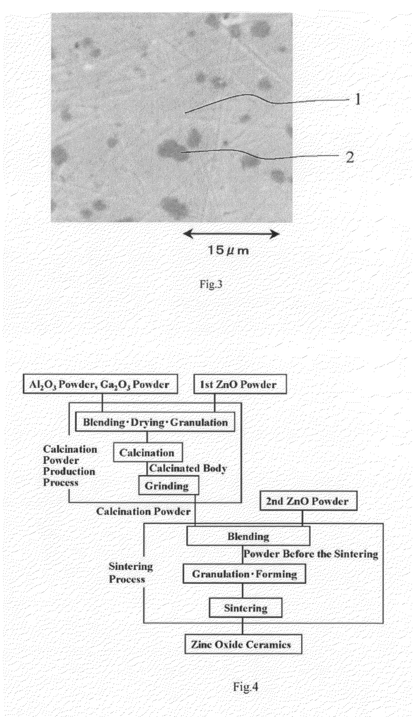
[0104]In the zinc oxide ceramics concerning the 2nd embodiment, another element is also doped simultaneously in addition to the dopant in the zinc oxide ceramics conserning the 1st embodiment (for example, Al). Hereafter, the dopant used in the 1st embodiment (for example, Al) is called the 1st dopant, and another dopant used here is called the 2nd dopant. The 2nd dopant is used here to improve weather resistance, for example, heat resistance or moisture resistance of the ZnO electrodes. The 2nd dopants which bring these effects may be one or more kinds among Al, Ga, In, Ti, Si, Ge, and Sn, excepting the element used as the 1st dopant. Especially as the 2nd dopant, Ga or In is used preferably.

[0105]In the manufacturing method of zinc oxide ceramics concerning the 2nd embodiment when Al is selected as the 1st dopant and Ga is selected as the 2nd dopant, as shown in FIG. 4, both Al2O3 powder and Ga2O3 powder are blended with the 1st ZnO powder simultaneously, instead...

3rd embodiment

The 3rd Embodiment

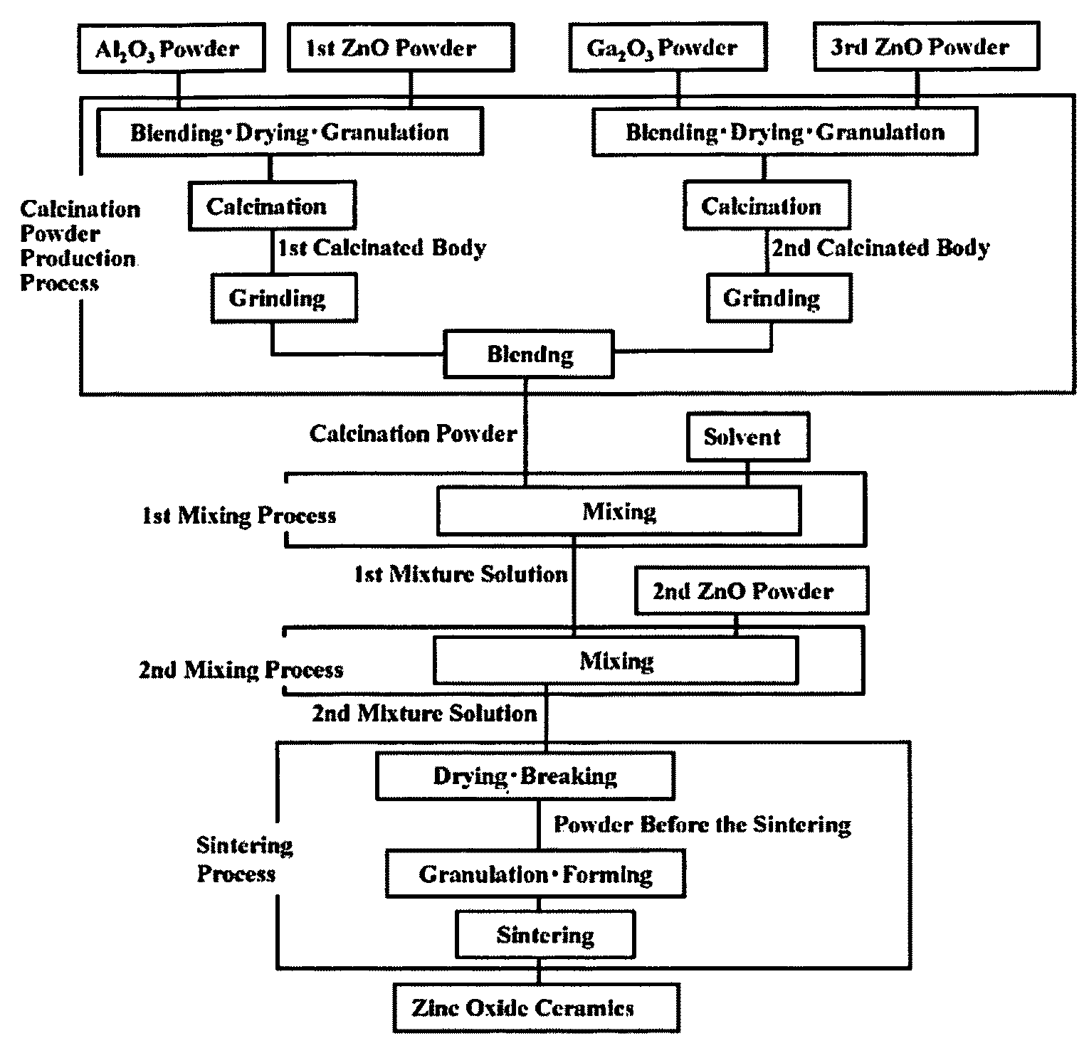
[0130]Similar zinc oxide ceramics can also be obtained by another manufacturing method concerning the 3rd embodiment instead of by the manufacturing method of the 1st or the 2nd embodiment. This example is shown in FIG. 7. By this manufacturing method, the dispersibility of the 1st dopant and the 2nd dopant in the zinc oxide ceramics can be improved further, and the abnormal discharge can be suppressed further.

[0131]Here, the calcination powder produced by the calcination powder production process similar to that of the 2nd embodiment (FIG. 4) is dissolved in a solvent, mixed by ball mill etc., and the 1st mixture solution is produced (1st mixing process). The 2nd ZnO powder is dissolved in the 1st mixture solution, they are mixed with a ball mill etc., and the 2nd mixture solution is produced (2nd mixing process). In the sintering process, this 2nd mixing solution is dried and broken into powder and the powder before the sintering is produced, by adjusting the par...


PUM

PropertyMeasurementUnit
Temperatureaaaaaaaaaa
Lengthaaaaaaaaaa

Abstract

Densified zinc oxide ceramics can be obtained so that transparent electrodes with good characteristics can be obtained using the ceramics as a sputtering target. This manufacturing method is used to manufacture the zinc oxide ceramics doped with Al in ZnO. This method comprises, calcination powder production process by which calcination powder is produced after blending Al2O3 powder and a 1st ZnO powder and by calcinating them, and sintering process by which said zinc oxide ceramics are manufactured after sintering formed body composed of powder before the sintering which is made by blending said calcination powder and a 2nd ZnO powder. Here, the ceramics are manufactured not by sintering a formed body composed of Al2O3 powder and ZnO powder, but by sintering the formed body composed of the calcination powder containing ZnAl2O4 phase and ZnO powder.

Description

BACKGROUND OF THE INVENTION[0001]1. Field of the Invention[0002]This invention relates to zinc oxide ceramics for a sputtering target by which transparent electrodes are formed by sputtering method, and also to a manufacturing method for the same.[0003]2. Description of the Related Art[0004]Electrodes with both high conductivity and high transparency of light (transparent electrodes) are used for liquid crystal displays or solar cells. As materials with such characteristics, oxide materials, such as In2O3—SnO2 (ITO), ZnO-B2O3 (BZO), and ZnO—Al2O3 (AZO), are known, for example. After such a material is formed as a thin film on a liquid crystal display or a solar cell by sputtering method, it is patterned and becomes a transparent electrode. In the sputtering process, a substrate (in this case, liquid crystal display etc.) on which a thin film is formed, is set facing the sputtering target (hereafter, target) in a sputtering apparatus. Then gas discharge is generated between these, an...

Claims


Application Information

Patent Timeline
IPC IPC(8): C04B35/10C04B35/01C04B35/14C04B35/64C23C14/34
CPCC04B35/453H01L31/022483C04B35/62685C04B2235/3217C04B2235/3222C04B2235/3232C04B2235/3234C04B2235/3284C04B2235/3286C04B2235/3287C04B2235/3293C04B2235/3418C04B2235/3427C04B2235/5409C04B2235/656C04B2235/77C04B2235/80C23C14/086C23C14/3414C04B35/62675C23C14/34
Inventor FUKUSHIMA, HIDEKO
Owner HITACHI METALS LTD
Why Eureka
Try Eureka