Procedure and apparatus for in-situ monitoring and feedback control of selective laser powder processing

a selective laser and monitoring technology, applied in the direction of additive manufacturing processes, manufacturing tools, manufacturing data acquisition/processing, etc., can solve the problems of liquid material spreading in the underlying powder material, overheating at the overhang plane, and dross that is formed, so as to improve the quality of the piece

Inactive Publication Date: 2009-08-20
KRUTH JEAN PIERRE +1
View PDF11 Cites 350 Cited by
  • Summary
  • Abstract
  • Description
  • Claims
  • Application Information

AI Technical Summary

Benefits of technology

[0015]It is the aim of the present invention to provide an apparatus and method which makes it possible to solve the problems of the state of the art and to improve the quality of the piece to be built by controlling an SLPP process using a signal reflecting the melt zone geometry.

Problems solved by technology

One of the major problems that are encountered in SLPP processes, especially in SLM, is the dross that is formed when overhang planes are scanned.
As a result, overheating occurs at the overhang plane, since the heat sink is much too low compared to the added energy.
Therefore, the melt zone becomes much too large and capillary and gravity forces result in liquid material spreading in the underlying powder material.
After solidification, the dross remains and causes a very poor surface finish requiring a post treatment
An other problem that occurs in SLPP is the excess energy that is directed to the powder surface when small vectors are used to scan small features.
Therefore, less time exist for conducting the heat away from the scanning area, and an accumulation of heat occurs.
As a result, the melt zone may become too large and powder particles outside the part contour will also be consolidated, leading to geometric inaccuracies and superfluous material.
Other examples of defects that occur in SLPP technologies are the splitting of the melt zone, due to the surface tension driven Rayleigh instability, resulting in ‘balling’ effects and a bad surface quality or even in process breakdown and the problem of neighbouring powder particles being sucked into the melt zone due to capillary forces resulting in a melt track that is too wide and in a lack of powder next to the melt track.
No possibility exists to automatically adapt the scanning parameters, during the execution of the process, based on information that can be extracted from the process.
Continuous variations of the border conditions cannot be compensated, and variations of the laser scanning parameters during the scanning of a vector are impossible.
Moreover, fluctuations in e.g. powder absorption coefficient or room temperature, that cannot be predicted a priori, before the execution of the process, cannot be compensated without the use of feedback control.

Method used


Image

  • Procedure and apparatus for in-situ monitoring and feedback control of selective laser powder processing
  • Procedure and apparatus for in-situ monitoring and feedback control of selective laser powder processing
  • Procedure and apparatus for in-situ monitoring and feedback control of selective laser powder processing

Examples


application examples

ILLUSTRATIVE EMBODIMENT AND APPLICATION EXAMPLES

[0108]Following illustrations show how the coaxial optical system can be used in case of the Selective Laser Melting process, to either observe the process or to actively control the process by adapting one or more adjustable process parameters based on the information recorded by a detector from the optical system. As a first illustration, a possible embodiment of the sensor system will be described. Next, a SLM monitoring experiment will be described and finally, the use of the sensor system for feedback process control will be illustrated.

example 1

Possible Embodiment of the Coaxial Optical System

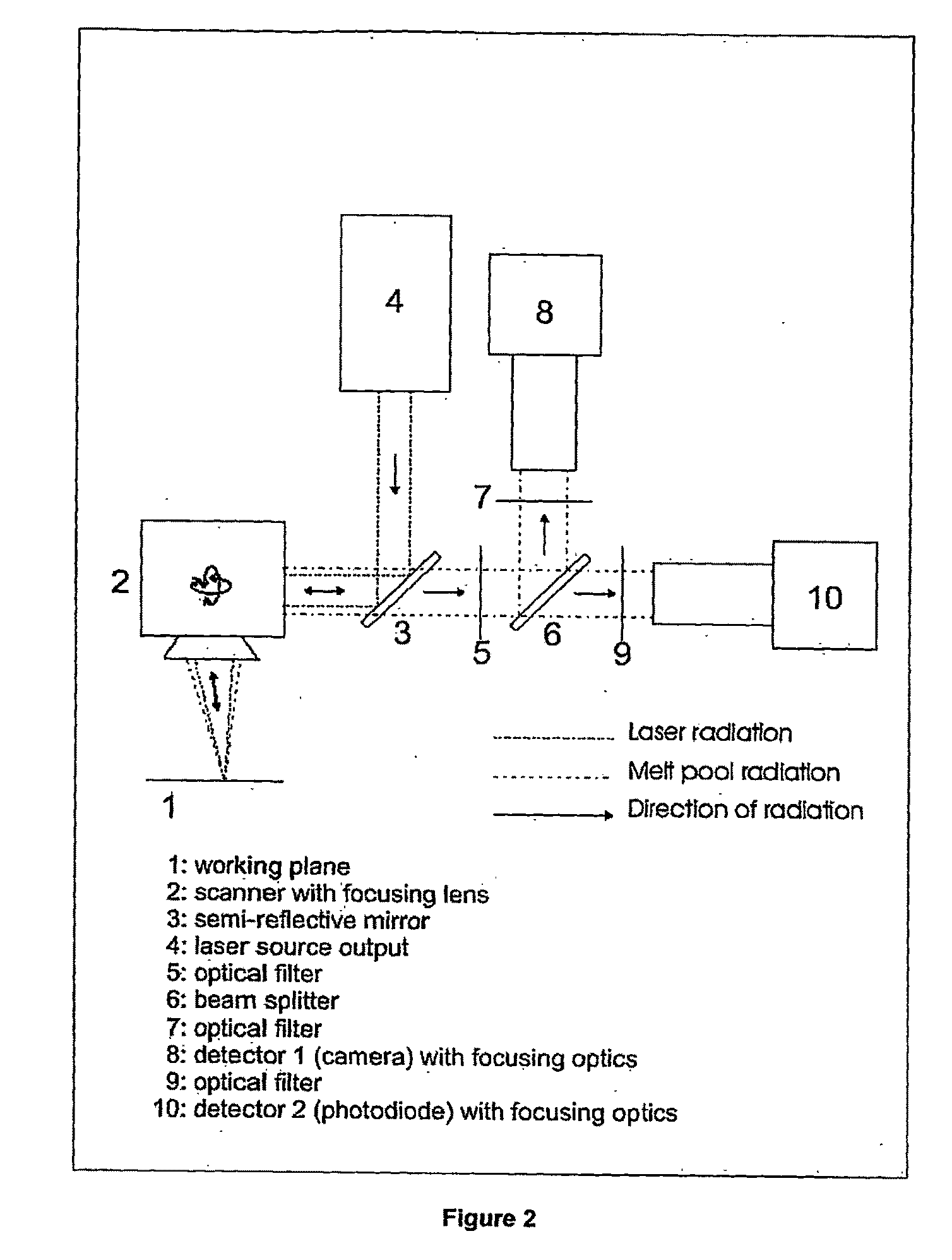
[0109]FIG. 2 shows a possible realization of the coaxial optical system. Following items 4: laser output, 5: optical filter, 6: beam splitter, 7: optical filter, 8: CMOS camera with focusing lens, 9: optical filter, 10: photodiode module. The photodiode that is used in this realization is a planar photodiode with an active area of 10 mm by 10 mm. The use of this large integrating area, together with the use the specific lens system, ensures that radiation is captured by the photodiode from a zone of about 4 mm by 4 mm around the moving laser spot. The dimensions of the area around the laser spot that is projected on the photodiode may differ from 4 mm by 4 mm. However, an observation zone that is too large may cause the photodiode to capture radiation from heated or molten material at a certain distance that does not belong to the melt zone. In that case, the process variable that is measured might be distorted by the radiation of the...

example 2

Use of the Coaxial Optical System for Observation and Study of the Selective Laser Melting Process

[0118]The coaxial optical system can be used to observe and study the behaviour of the melt zone of the SLM process. This may be done for several reasons, including studying the stability of the melt zone and the influence of the process parameters (like scanning velocity and laser power), studying the effect of the powder composition on the melt zone shape and stability, etc.

[0119]For these purposes, a camera detector is preferably used instead of an integrating sensor. FIG. 7 shows an example of a melt zone observation experiment using the high speed CMOS camera. Two experiments were done to examine the influence of the addition of a small amount of silicon to an iron powder mixture. All scanning and process parameters were identical for the two experiments, the only difference being the powder composition. It is clear that the addition of a small amount of silicon powder to the iron ...


PUM

PropertyMeasurementUnit
scanning velocitiesaaaaaaaaaa

Abstract

The present invention relates to a method and a device to monitor and control the Selective Laser Powder Processing. A Selective Laser Powder Processing device comprising a feedback controller to improve the stability of the Selective Laser Powder Processing process is presented. A signal reflecting a geometric quantity of the melt zone is used in the feedback controller to adjust the scanning parameters (e.g. laser power, laser spot size, scanning velocity, . . . ) of the laser beam (4) in order to maintain the geometric quantity of the melt zone at a constant level. The signal reflecting the geometric quantity of the melt zone can also be displayed in order to monitor the Selective Laser Powder Processing process. The present invention allows for the production of three-dimensional objects from powder material and improves the state of the art by compensating variations of the border conditions (e.g. local heat conduction rate) by a feedback control system based on a geometric quantity of the melt zone resulting in e.g. a lower amount of dross material when overhang planes are scanned.

Description

FIELD OF THE INVENTION[0001]The present invention relates to a method and a device to monitor and control Selective Laser Powder Processing technologies.BACKGROUND OF THE INVENTION[0002]Selective Laser Powder Processing (SLPP) refers to a computer controlled production process that can be used to produce three-dimensional objects from powder material. Three-dimensional objects are programmatically divided in two-dimensional sections that are successively processed and connected together. In order to process a two-dimensional slice, a laser beam—that is being focussed towards a building platform—is deflected using computer controlled scanning mirrors. A powder deposition system, comprising a moving roller, a blade or any other powder spreading device and a powder container, is used to apply the successive powder layers on top of each other. FIG. 1 shows the schematic layout of typical Selective Laser Powder Processing machine.[0003]Different types of SLPP technologies exist, the most...

Claims


Application Information

Patent Timeline
Patent Type & Authority Applications(United States)
IPC IPC(8): B23K26/02B23K26/00
CPCB22F3/1055B23K26/03B23K26/034B22F2003/1057B23K26/0665B29C67/0077B23K26/036B23K26/0342B29C64/153B29C64/393B23K26/342Y02P10/25B22F10/28B22F10/36B22F12/49B22F12/44B22F12/90
Inventor KRUTH, JEAN-PIERREMERCELIS, PETER
Owner KRUTH JEAN PIERRE
Why Eureka
Try Eureka