
Resin composition for laser engraving, resin printing plate precursor for laser engraving, relief printing plate and method for production of relief printing plate

Inactive Publication Date: 2009-09-03
FUJIFILM CORP
View PDF21 Cites 16 Cited by
  • Summary
  • Abstract
  • Description
  • Claims
  • Application Information

AI Technical Summary

Benefits of technology

[0045]It is believed that the laser engraving (particularly, with a near-infrared laser) conducted in the invention is composed of five processes of (1) light absorption by a compound having an absorption maximum wavelength in a range of 700 to 1,300 nm, (2) light-to-heat conversion by the compound having an absorption maximum wavelength in a range of 700 to 1,300 nm, (3) heat transfer from the compound having an absorption maximum wavelength in a range of 700 to 1,300 nm to a binder adjacent thereto, (4) thermal decomposition of the binder, and (5) dissipation of the decomposed binder. Since the binder (A) has the low temperature thermal decomposition property and depolymerization property as described above, the process (4) is accelerated by the low temperature thermal decomposition property and a low molecular monomer (largely volatilizes at less than 250° C.) generated by the depolymerization volatilizes immediately to progress extremely effectively the process (5). It is believed that due to these two advantageous effects the laser engraving sensitivity becomes extremely high.
[0046]Moreover, it is believed that the laser engraving area becomes extremely high temperature and the thermal decomposition and depolymerization of the binder (A) is accelerated (decrease in thermal decomposition temperature) with the oxy compound (B).
[0047]As an example of the binder (A), a polymer obtained by a polymerization reaction using a hydroxycarboxylic acid as one of the raw materials is described below.
[0048]As PHA of the binder (A), a polymer having a repeating monomer unit represented by formula (a) shown below is preferable.
[0049]In formula (a), n represents an integer of 1 to 5, R1 represents a hydrogen atom, an alkyl group or an alkenyl group. The alkyl group and alkenyl group each preferably has from 1 to 20 carbon atoms. The polymer includes a homopolymer wherein the combination of R1 and n in the repeating monomer unit is same and fixed and a copolymer having at least two different repeating monomer units with respect to the combination of R1 and n. The copolymer may be a random, block, alternative or graft polymer. The molecular weight of PHA is ordinarily in a range from 500 to 5,000,000 g / mol, preferably from 1,000 to 2,500,000 g / mol, more preferably from 2,500 to 1,000,000 g / mol.
[0050]The PHA for use in the invention includes poly-3-hydroxybutyrate, poly-3-hydroxyvalerate, poly-3-hydroxyheptanoate, poly-3-hydroxyoctanoate, poly-4-hydroxybutyrate, poly(3-hydroxybutyrate-co-3-hydroxyvalerate), poly(3-hydroxybutyrate-co-4-hydroxybutyrate), poly(3-hydroxybutyrate-co-3-hydroxyoctanoate) and other copolymers. The copolymer of PHA contains ordinarily 40% or more and less than 100%, preferably from 60 to 98%, of 3-hydroxybutyrate monomer.

Problems solved by technology

However, since it is apt to be deformed by the application of stress, a printing pressure is necessary to be low.
Since the analog plate making requires an original film using a silver salt material in many cases, the time and cost for producing the original film are necessary.
Further, in order to develop the original film, a chemical treatment is required and treatment of the waste liquid of development is also needed, the analog plate making is disadvantageous in view of environmental health.
Although the mask CTP system resolves the problems relating to the process of producing the original film described above, the problems on the treatment of waste liquid resulting from the development of the photosensitive elastomer layer or the photosensitive resin layer still remain.
Further, in case of the flexographic printing plate, since a chlorine solvent, for example, trichloroethylene is used in the development in many instances, the system is also disadvantageous in view of working health.
However, since the developing speed of the heat development system is extremely low in comparison with that of the solvent development system, other problems in that the working efficiency is poor and in that a complicated and costly development apparatus is required.
As a problem of the direct engraving CTP system, it is illustrated that the seed of laser engraving is low.
Although the improvement in laser engraving sensitivity is intended by using the foam having low density, a problem arises in that because of using the material of low density, the strength for a printing plate is insufficient and printing durability is severely impaired.
However, a problem arises in that the strength for a printing plate is apt to be insufficient because of the material system including the gas.
Further, since the gas has a property of easy expansion with heat in comparison with a solid, even when microspheres having a high heat deformation initiation temperature are used, change in the volume due to fluctuation of the outer temperature can not be avoided and thus it is not suitable to use as a printing plate which is required stability of the accuracy of thickness.
Although the improvement in laser engraving sensitivity is intended by adding the polymer filler having a low depolymerization temperature, the use of such a polymer filler makes a concavity and convexity on the surface of printing plate precursor which seriously influences printing quality.

Method used


Image

  • Resin composition for laser engraving, resin printing plate precursor for laser engraving, relief printing plate and method for production of relief printing plate
  • Resin composition for laser engraving, resin printing plate precursor for laser engraving, relief printing plate and method for production of relief printing plate
  • Resin composition for laser engraving, resin printing plate precursor for laser engraving, relief printing plate and method for production of relief printing plate

Examples


example 1

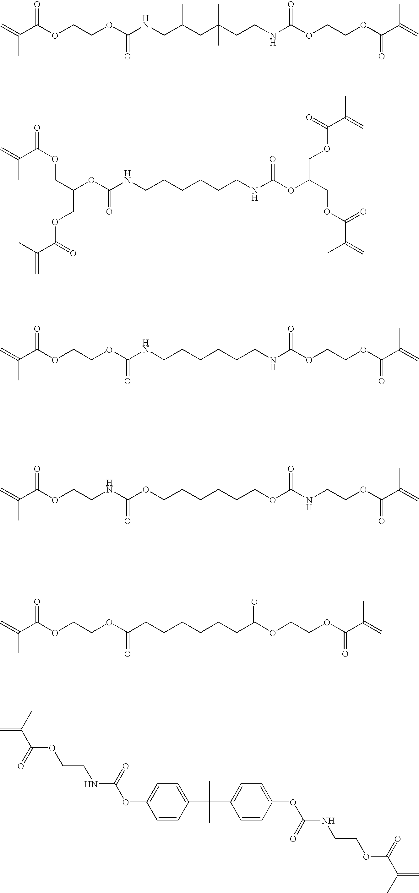
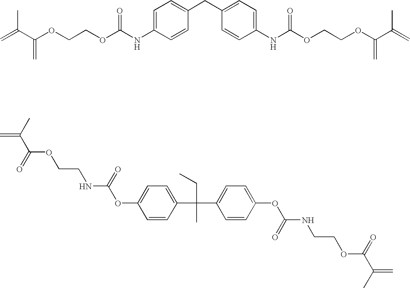
[0280]In a three-necked flask equipped with a stirring blade and a condenser were put 10 g of Landy PL-2000 (emulsion (aqueous dispersion) of polylactic acid, produced by Miyoshi Oil and Fat Co., Ltd.) as the binder (A), 40 g of Gosenal T-215 (PVA derivative, produced by Nippon Synthetic Chemical Industry Co., Ltd.) as the binder (A′), 0.75 g of Ketjenblack EC600JD (produced by Lion Corp.) as the light-to-heat conversion agent (D), 20 g of diethylene glycol as the plasticizer (F) and 35 g of water and 12 g of ethanol as the solvents and the mixture was heated at 70° C. for 120 minutes with stirring to dissolve the polymer. To the solution were further added 28 g of the compound shown below which was an ethylenically unsaturated monomer as the polymerizable compound (C) and 1.6 g of Irgacure 184 (α-hydroxyketone, produced by Ciba-Geigy Corp.) as the polymerization initiator (E) and 1.0 g of magnesium oxide heavy (produced by Wako Pure Chemical industries, Ltd.) as the oxy compound (B...

example 2

[0285]The same procedures were performed as in Example 1 except for changing the magnesium oxide to calcium oxide (produced by Wako Pure Chemical industries, Ltd.) as the oxy compound (B).

example 3

[0286]The same procedures were performed as in Example 1 except for changing the magnesium oxide to Neostan U-600 (a mixture of bismuth tris(2-ethylhexanoate) and 2-ethylhexanoic acid, produced by Nitto Kasei Co., Ltd.) as the oxy compound (B).


PUM

PropertyMeasurementUnit
Thicknessaaaaaaaaaa
Angleaaaaaaaaaa
Wavelengthaaaaaaaaaa

Abstract

A resin composition for laser engraving includes a binder polymer including a polyester, and an oxy compound of at least one of metal and metalloid selected from Groups 1 to 16 of periodic table.

Description

FIELD OF THE INVENTION[0001]The present invention relates to a resin composition for laser engraving, a resin printing plate precursor for laser engraving, a relief printing plate and a method for production of a relief printing plate.BACKGROUND OF THE INVENTION[0002]As a method of preparation of a relief printing plate by forming a concavity and convexity on the surface, a so-called “analog plate making”, that is, a method in which a photosensitive elastomer composition or photosensitive resin composition is exposed to ultraviolet light through an original film to selectively cure the image area and the uncured area is removed with a developer is well known.[0003]The photosensitive elastomer composition contains an elastomeric polymer, for example, a synthetic rubber, as a carrier and since the relief image formed therefrom is flexible, the printing plate is referred to as a flexographic printing plate.[0004]The flexographic printing plate has an aptitude for water-based ink, alcoh...

Claims


Application Information

Patent Timeline
IPC IPC(8): B32B3/10G03F7/26G03F7/004
CPCB41C1/05B41N1/12C08K3/22C08K5/0091C08K5/098Y10T428/24802C08L67/04
Inventor SUGASAKI, ATSUSHI
Owner FUJIFILM CORP
Learn More