

Method of producing chemical product and continuous fermentation apparatus
a technology of continuous fermentation and chemical products, which is applied in specific use bioreactors/fermenters, biomass after-treatment, biofuels, etc., can solve the problems of reducing productivity and yield, increasing the concentration of a product in a culture, and difficult to maintain high yield and high productivity
- Summary
- Abstract
- Description
- Claims
- Application Information
AI Technical Summary
Problems solved by technology
Method used
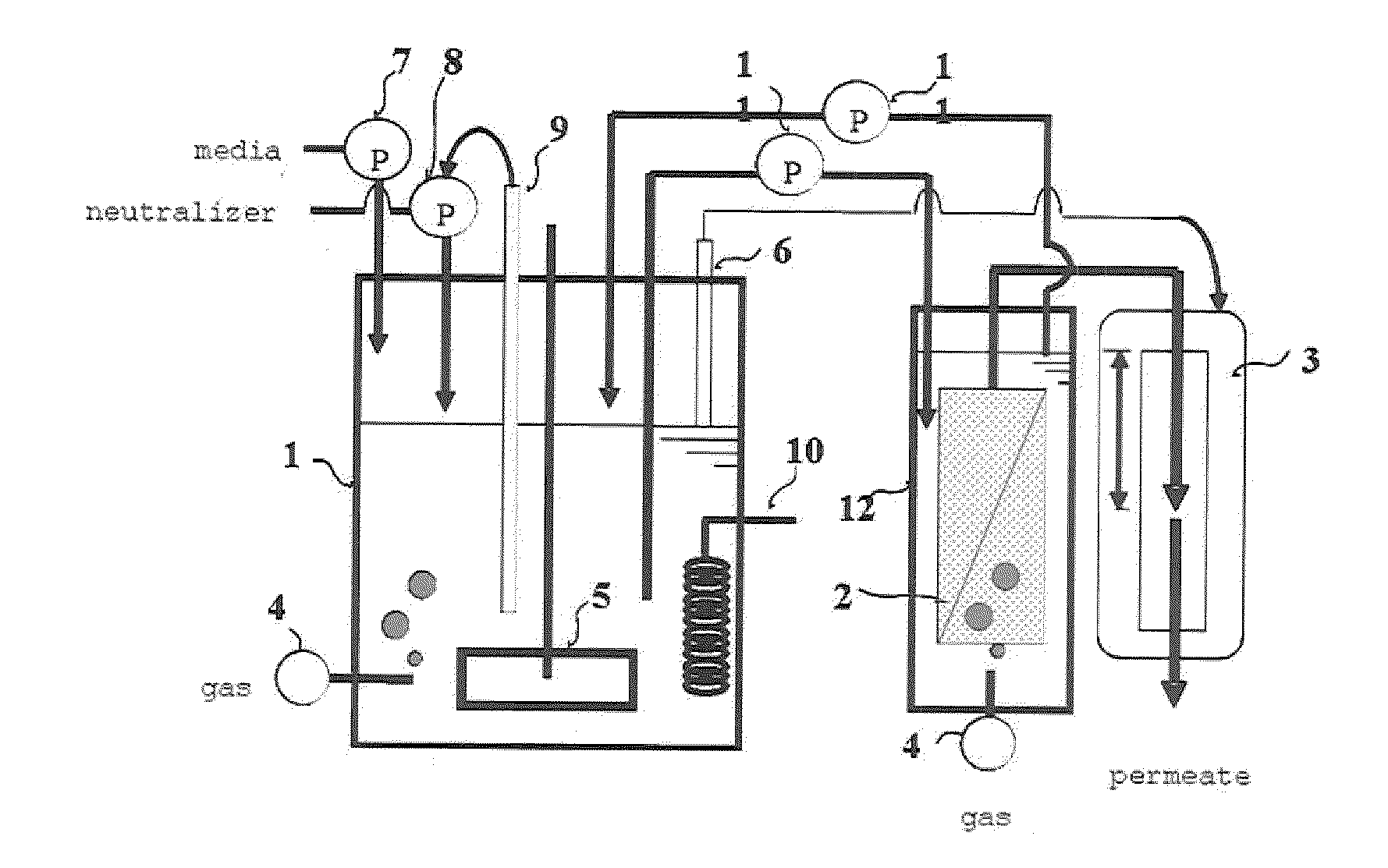
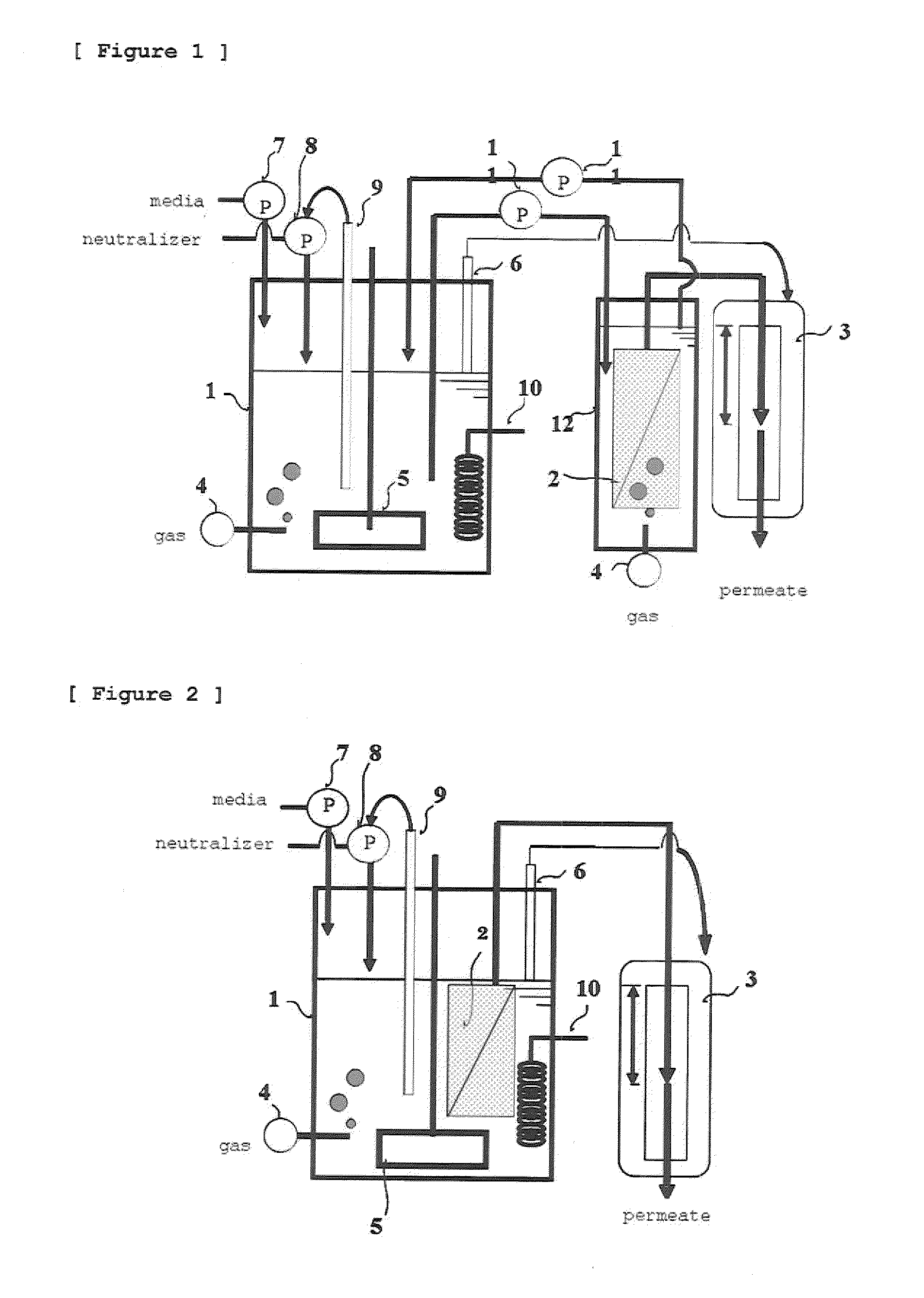
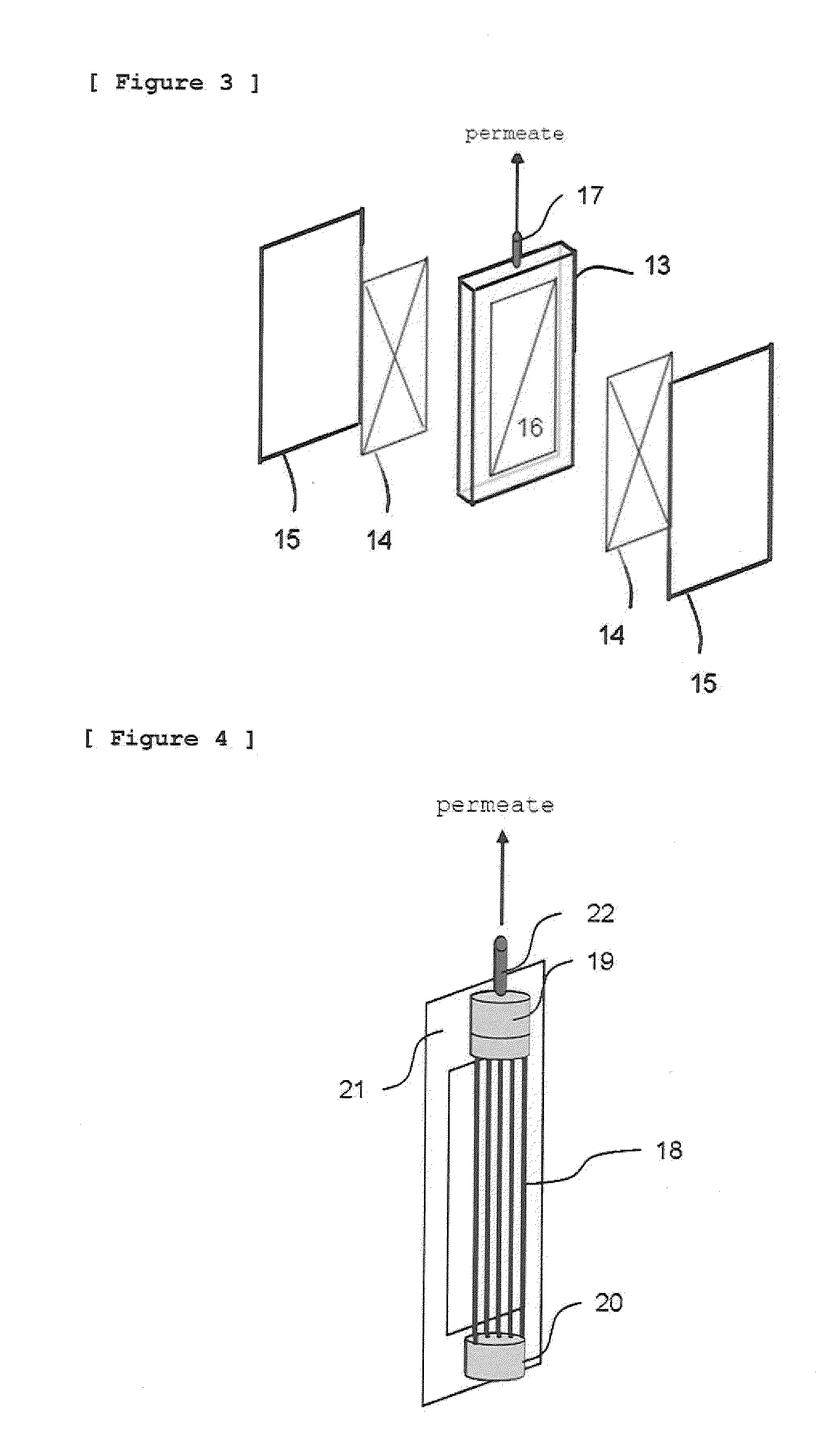
Image

Examples
reference example 1
Preparation of a Yeast Strain Having an Ability to Produce L-Lactic Acid
[0177]A yeast strain having an ability to produce L-lactic acid was created in the following manner. A human-derived LDH gene was ligated downstream from a PDC1 promoter on yeast genome thereby creating a yeast strain having an ability to produce L-lactic acid. Polymerase chain reaction (PCR) was carried out using La-Taq (Takara Shuzo Co., Ltd.) or KOD-Plus-polymerase (TOYOBO CO., LTD.) according to its attached instructions.
[0178]After an established cell line of human breast cancer (MCF-7) was cultured and recovered, the total RNA was extracted using TRIZOL Reagent (Invirogen). Using the resulting total RNA as a template, reverse transcription reaction was carried out using SuperScript Choice System (Invitrogen), to synthesize cDNA. Details of the operation were in accordance with protocols attached thereto. The cDNA thus obtained was used as an amplification template for subsequent PCR.
[0179]An L-ldh gene was...
reference example 2
Preparation of a Porous Membrane (No. 1)
[0185]A polyvinylidene fluoride (PVDF) resin and N,N-dimethylacetamide were used as a resin and solvent respectively and stirred sufficiently at a temperature of 90° C. to give a stock solution having the following composition:
Polyvinylidene fluoride: 13.0% by weight, and
N,N-Dimethylacetamide: 87.0% by weight
[0186]Then, the stock solution was cooled to a temperature of 25° C., then applied onto a polyester fiber nonwoven fabric having a density of 0.48 g / cm3 and a thickness of 220 μm attached previously to a glass plate, and was immediately dipped for 5 minutes in a coagulation bath at a temperature of 25° C. having the following composition, to give a porous base material having a porous resin layer formed thereon.
Water: 30.0% by weight
N,N-Dimethylacetamide: 70.0% by weight
[0187]This porous base material was detached from the glass plate, dipped 3 times in hot water at a temperature of 80° C., thereby being washed to remove N,N-dimethylacetam...
reference example 3
Preparation of a Porous Membrane (No. 2)
[0191]A polyvinylidene fluoride (PVDF) resin was used as resin, polyethylene glycol (PEG) having a molecular weight of about 20,000 as a pore-forming agent, N,N-dimethylacetamide as solvent, and purified water as non-solvent, and these materials were stirred sufficiently at a temperature of 90° C. to give a stock solution having the following composition:
Polyvinylidene fluoride: 13.0% by weight
Polyethylene glycol: 5.5% by weight
N,N-Dimethylacetamide: 78.0% by weight, and
Purified water: 3.5% by weight.
[0192]Then, the stock solution was cooled to a temperature of 25° C., then applied onto a polyester fiber nonwoven fabric having a density of 0.48 g / cm3 and a thickness of 220 μm, immediately dipped for 5 minutes in purified water at 25° C., dipped 3 times in hot water at 80° C., thereby being washed to remove N,N-dimethylacetamide and polyethylene glycol to give a separation membrane.
[0193]The surface of the porous resin layer in an area of 9.2 μ...
PUM
| Property | Measurement | Unit |
|---|---|---|
| pore size | aaaaa | aaaaa |
| pore size | aaaaa | aaaaa |
| pore size | aaaaa | aaaaa |
Abstract
Description
Claims
Application Information