

Patterning process
a pattening process and resist technology, applied in the field of resist pattening process, can solve the problems of inability to use reverse film material, inability to form fine patterns, and tendency to easily vary in dimension, so as to achieve the effect of high precision and greatly simplified process
- Summary
- Abstract
- Description
- Claims
- Application Information
AI Technical Summary
Benefits of technology
Problems solved by technology
Method used
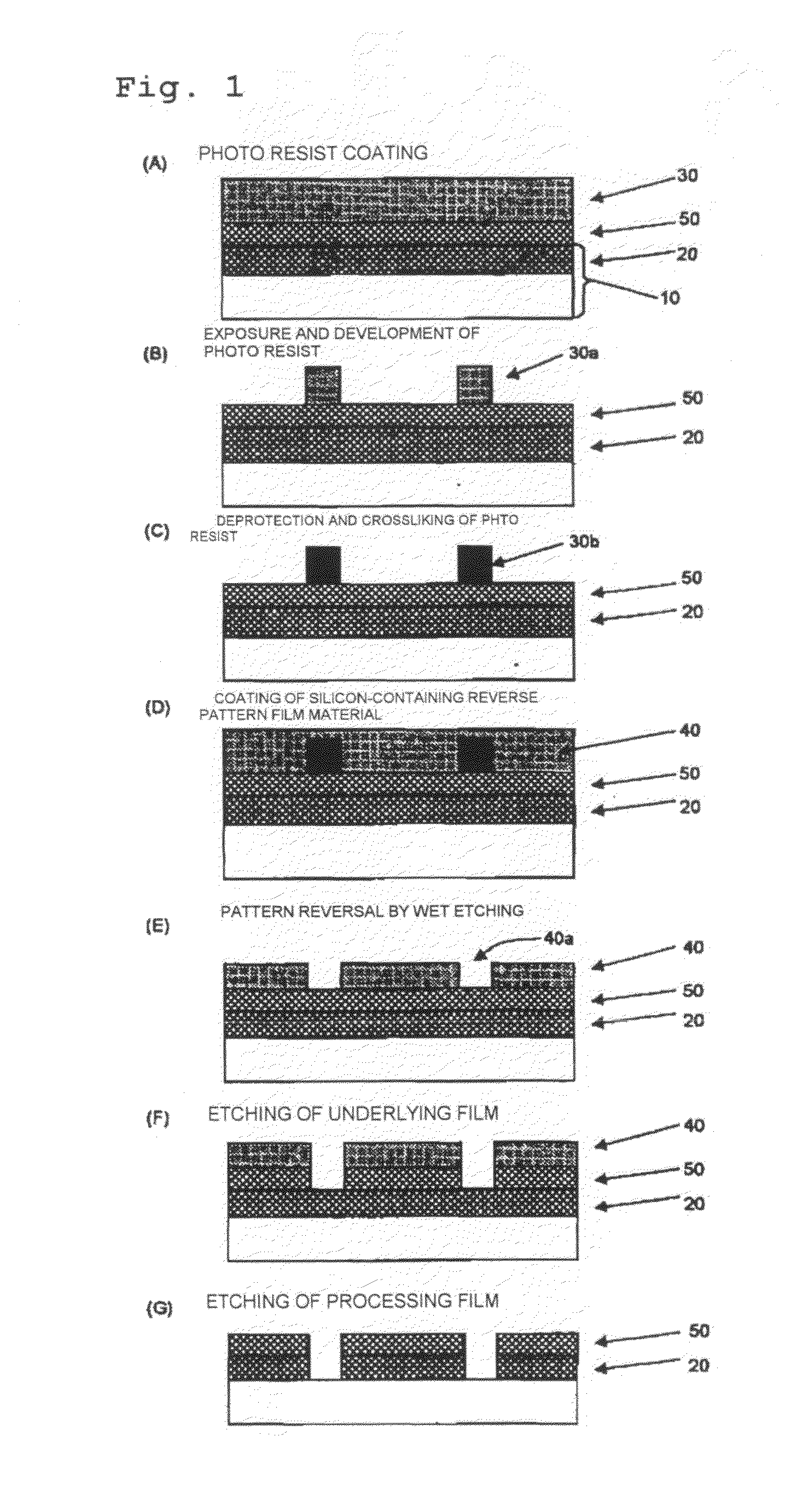
Image

Examples
examples
[0319]In the following, the present invention will be explained specifically by Synthetic Examples, Examples, and Comparative Examples, but the present invention is not restricted to the following Examples and so forth. Here, the weight-average molecular weight (Mw) is shown in terms of the weight-average molecular weight of polystyrene obtained by a GPC method.
Synthetic Examples
[0320]By combining each monomer, a co-condensation reaction was carried out in the presence of an acetic acid catalyst in water / ethanol. The resulting reaction mixture was washed by water repeatedly until an organic film became neutral, and then concentrated to obtain an oligomer for a polymer used in a reverse film.
[0321]This was diluted by toluene, and heated with addition of potassium hydroxide under reflux. After cooled, the resulting reaction solution was diluted by methyl isobutyl ketone, washed by water repeatedly until an organic film became neutral, and then concentrated to obtain a polymer. The pol...
PUM
| Property | Measurement | Unit |
|---|---|---|
| wavelength | aaaaa | aaaaa |
| wavelength | aaaaa | aaaaa |
| wavelength | aaaaa | aaaaa |
Abstract
Description
Claims
Application Information