Method for fabricating a preform, a preform, an optical fiber and an amplifier

a technology of preforms and optical fibers, applied in the field of methods for fabricating preforms, preforms, optical fibers and amplifiers, can solve the problems of reducing the amount of power present in the optical signal, affecting the signal-to-noise ratio of an amplifier-based communication system, and not necessarily providing higher gain, so as to achieve low cost, improve the effect of performance and low cos

Active Publication Date: 2010-01-07
SILITEC FIBERS SA
View PDF14 Cites 16 Cited by
  • Summary
  • Abstract
  • Description
  • Claims
  • Application Information

AI Technical Summary

Benefits of technology

[0045]With this method, clustering of A / A-particles can be avoided even if provided in comparably high concentrations. The A / A-particles are homogenously distributed within the SiO2-A / A-mixture and later on in the A / A doped host medium, i.e. in the core and / or cladding parts of the preform or fiber. Hence A / A doped host media with significantly higher gain or attenuation can be fabricated. While providing excellent results the new method can be performed with little effort. At the same time the refractive index is also homogeneously distributed across the processed material.
[0046]Fibers derived from inventive optical media comprise therefore significantly improved properties, particularly in view of gain and beam quality of applied signals.

Problems solved by technology

Spontaneous emission occurs when ions in the excited state spontaneously relax to the ground state contributing to noise thus affecting the signal-to-noise ratio of an amplifier-based communication system.
Hence a higher concentration of RE-ions does not necessarily provide higher gain and reduced signal to noise.
There are many situations, however, in which it is necessary to utilize optical attenuator devices to reduce the amount of power present in the optical signal.
These common methods are not easily manageable and require considerable efforts.
Hence, besides high efforts for executing the described processes, significant restrictions result in view of the placement of the A / A-dopants.
While the geometry of the fibers can be designed as required, severe restrictions result for the location of the RE-dopants.
These restrictions are especially disadvantageous in view of the considerations relating to obtaining maximum gain and minimum noise with laser active optical fibers.
Further, with the above described vapour deposition processes it is difficult to obtain larger preforms that are suitably doped with A / A-materials.
It is particularly difficult to obtain optical fibers with multiple cores that are suitably doped with A / A-materials.
However, above a modest concentration, rare earth ion clustering and quenching become a problem.
It has been discovered that with known methods, desirable concentrations of rare earth dopants, i.e. desirable gains in optical media can still not be reached due to the described clustering problem.
Hence, the concentration of RE-dopants and consequently the gain of the rare earth doped host medium remains restricted.
Further it has been found that clustering problems also occur when doping a host medium with attenuation dopants.
Still further, a problem which so far did not find appropriate attention relates to a lack of homogeneity of the refractive indices of core and cladding material.
Inhomogeneities of the indices provided in the materials, which practically are not avoidable in deposition processes, may cause poor beam quality, particularly beam propagation deficiencies.

Method used


Image

  • Method for fabricating a preform, a preform, an optical fiber and an amplifier
  • Method for fabricating a preform, a preform, an optical fiber and an amplifier
  • Method for fabricating a preform, a preform, an optical fiber and an amplifier

Examples


Embodiment Construction

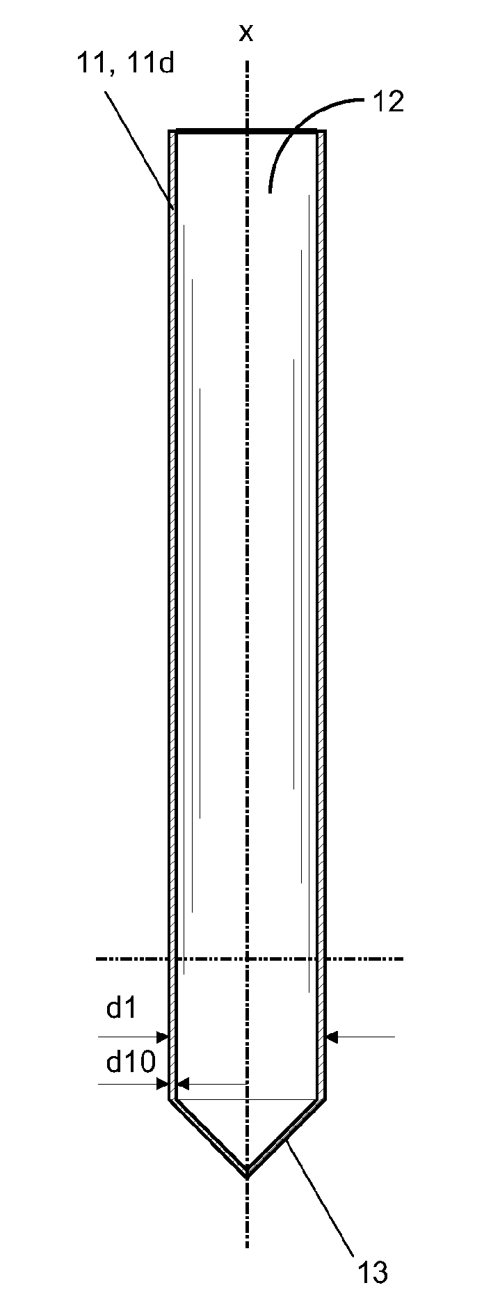
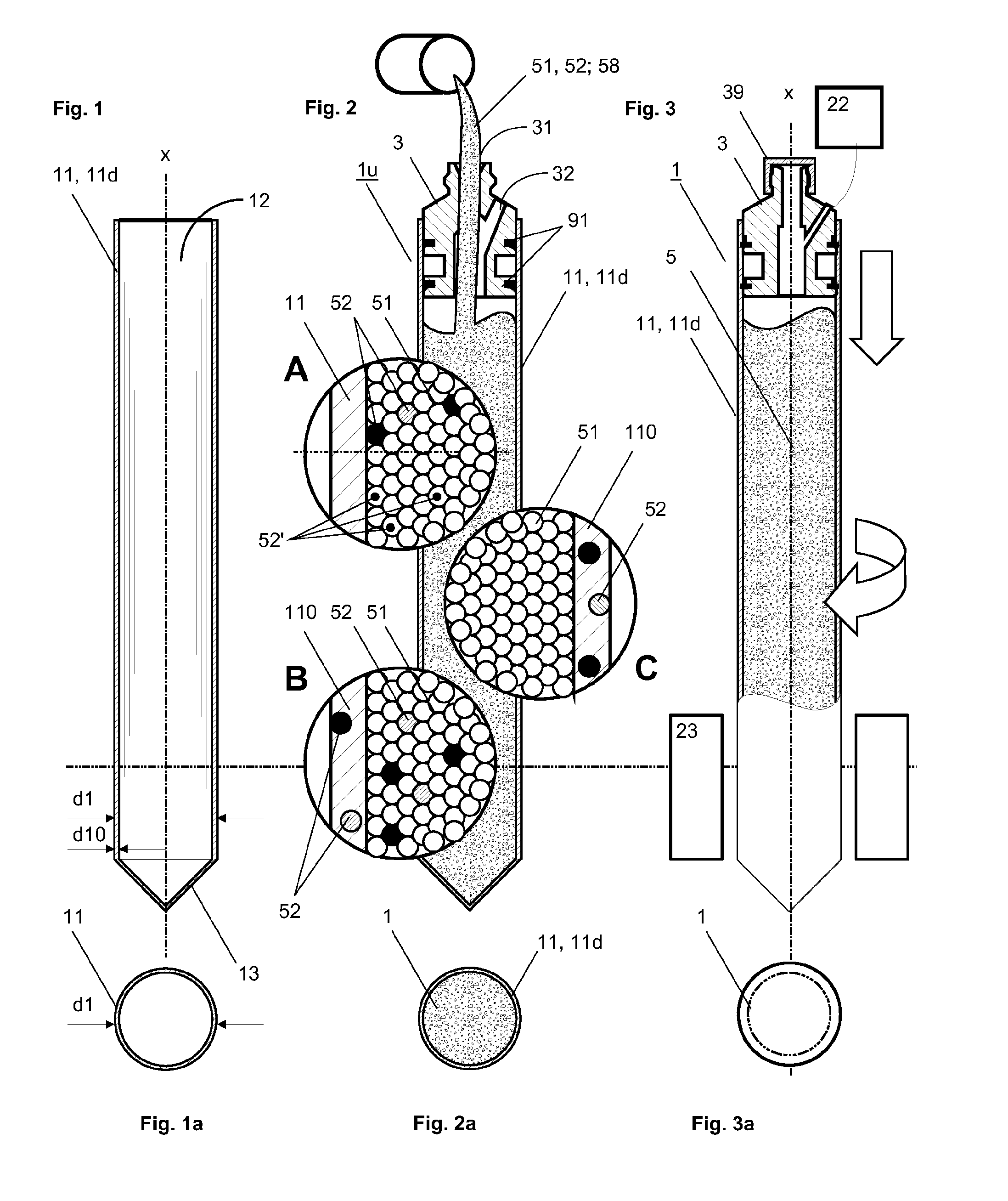
[0100]FIG. 1 shows a primary silica (SiO2) tube 11 having a longitudinal axis x, an outer diameter d1, a wall diameter d10, an interior space 12 and a closure 13 at its lower end, which is preferably made as one piece together with the primary silica tube 11. Optionally, as shown in FIG. 2, e.g. magnified sections B and C, the primary silica tube 11 may contain, enclosed in its walls, A / A-material 52 of one or numerous sorts, for purposes that are described below.

[0101]FIG. 2 shows the silica tube 11, 11d of FIG. 1 with an adjoiner 3 at its upper side comprising a first channel 31, through which primary silica grain 51 or an SiO2-A / A mixture 58, which will be described below with reference to FIG. 15 is filled into the interior space 12 of the silica tube 11. FIG. 2 further shows different options A, B and C of using a silica tube 1d and primary silica grain 51 that are differently doped with A / A-material 52, thus resulting in different localisations of different selectable A / A-mate...


PUM

PropertyMeasurementUnit
temperatureaaaaaaaaaa
sizeaaaaaaaaaa

Abstract

The present invention relates to a method and an apparatus for fabricating a preform (1,10,100) that can be used for drawing an active optical fiber (8). The present invention further relates to an active optical fiber (8), designed for amplification or attenuation purposes, drawn from said preform (1,10,100) and to an optical amplifier (600, 601) using a laser active optical fiber.

Description

[0001]The present invention relates to a method for fabricating a primary, secondary or higher order preform that can be used for drawing an active optical fiber that allows amplification or attenuation of an optical signal. The present invention further relates to a preform, an active optical fiber drawn from said preform and to an optical amplifier using said optical fiber.[0002]Fabrication of optical fibers, such as the fibers currently used in ultra high speed data communication networks, is described in [1], Mool C. Gupta, Handbook of PHOTONICS, CRC Press, 1997 Boca Raton, chapter 10.7, pages 445-449. Main process steps of optical fiber fabrication are fabricating a preform, drawing the fiber from the preform and coating the fiber with a material that protects the fiber from handling and from environmental influences.[0003]In the drawing process, the preform is fed from above into the drawing portion of a furnace while being drawn from the bottom using tractors. The fiber is th...

Claims


Application Information

Patent Timeline
Patent Type & Authority Applications(United States)
IPC IPC(8): C03B37/075
CPCC03B37/0122C03B37/01297C03B37/0279G02B6/02295C03B2201/40G02B6/02G02B6/02042C03B2201/34C03B37/012C03B37/027H01S3/067
Inventor SANDOZ, FREDERICPEDRIDO, CARLOSRIBAUX, PHILIPPEHAMEL, PHILIPPEOTHENIN, PETERROY, PHILIPPE VINCENTDEVAUTOUR, METHIEW
Owner SILITEC FIBERS SA
Why Eureka
Try Eureka